ElmoMC SimplIQ Digital Servo Drives-Bell Command Reference User Manual
Page 233
1
Current
command
Σ
Cogging
correction
2
Command to current
controller
Motor
currents
2
2
3
1
2
2
2
2
1
2
(
2
)
3
)
3
(2
I
phases
I
I
phase
I
or
I
s
−
−
+ +
+
LPF, 1
st
order
[2]
[1]
log 1
PL
CL
MC
τ
−
=
−
CL[1] - if current limit = PL[1]
or
0.9 CL[1]- if current limit = CL[1]
CL[1] continuous limit
PL[1] peak limit
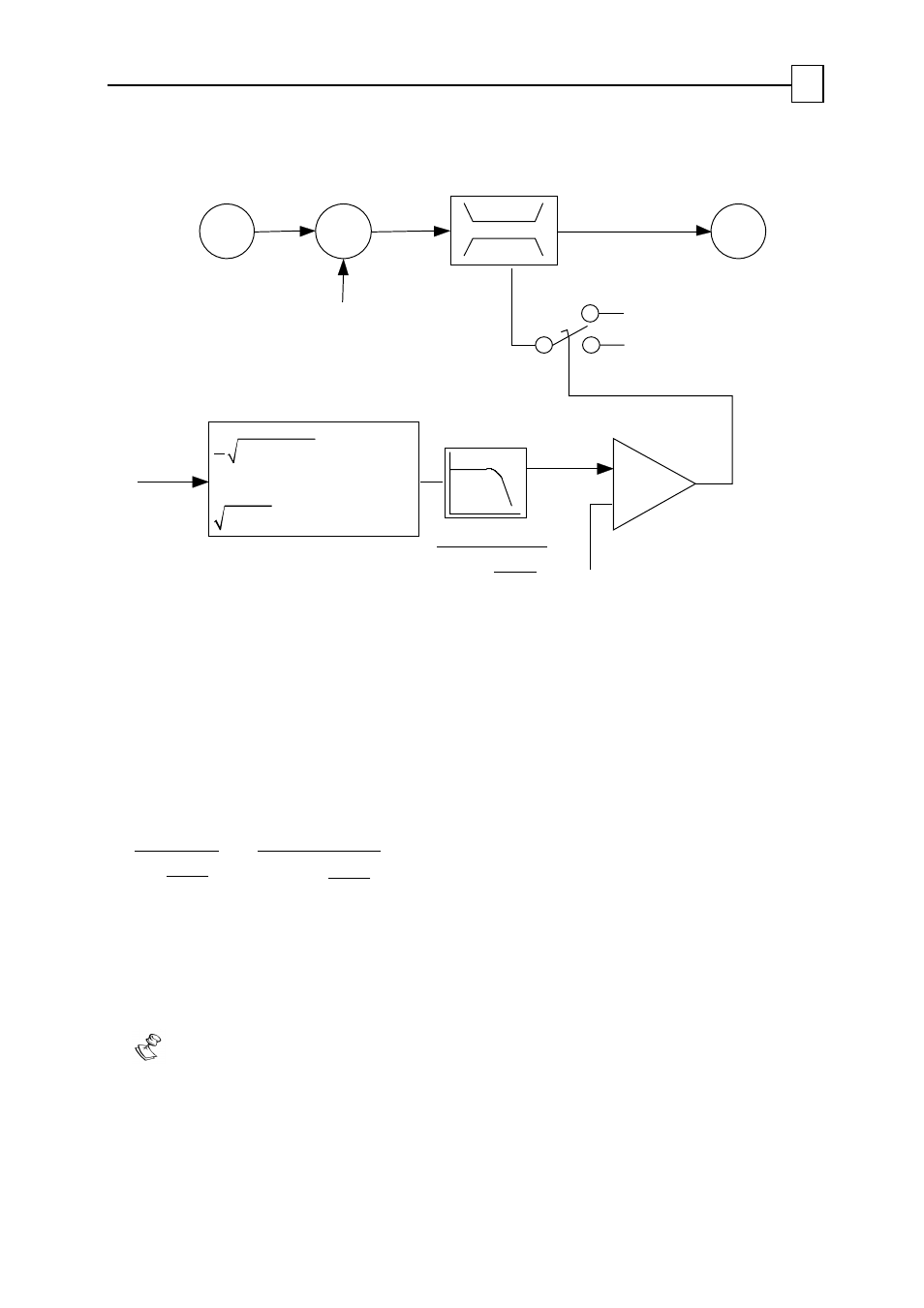
Figure 5-2: Current limiting mechanism
In the figure, we see that the RMS currents are averaged using a low-pass filter. When the
output of the filter crosses the threshold of CL[1], the current limit drops to CL[1]. It will
remain so until the averaged RMS current will fall below
[
.9
]
0
1
CL
×
The time constant of the averaging low-pass filter is taken as the minimum between
3sec
[1]
1
CL
MC
−
and
[2]
[1]
log 1
[1]
PL
CL
PL
−
−
, where MC is the maximum servo drive current, and
PL[2] programs the peak current maximum duration.
The value of
τ
is so that when a current demand of PL[1] is placed after a long period of
zero current, the current demand may be satisfied for PL[2] seconds.
For value of PL[2] close to MC, however, the peak current time is limited to 3 seconds.
Notes:
If, prior to the high current demand, the current demand was very close to CL[1],
the switch will occur almost instantaneously.
If the current demand is just greater than CL[1], and significantly less than PL[1],
the switch to current limiting may take a very long time.
SimplIQ for Steppers Application Note
Commutation and Pole Identification
MAN-STECR (Ver. 1.1)
34