Figure 15: chassis id and slot number – Allied Telesis AT-S97 User Manual
Page 105
AT-S85 and AT-S97 Management Software User’s Guide
105
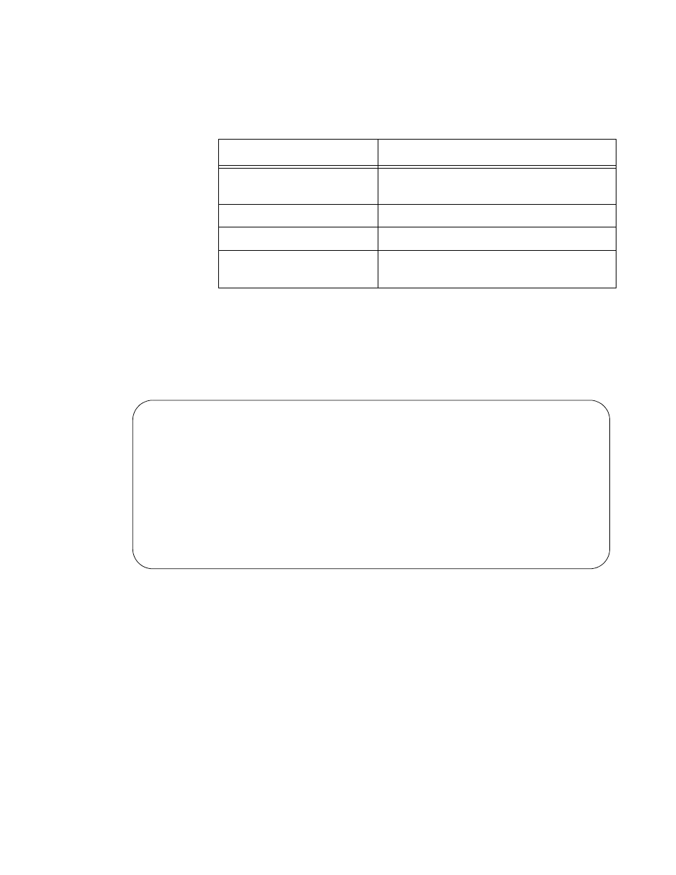
The table does not include empty media converter slots. The columns are
defined here:
Description of the Chassis and Slot Command
To view the current status of the channel ports on a media converter
module, including the status of the links between the channel ports and the
network devices, specify in the command both a chassis ID number and
the slot number of the module. Figure 15 is an example.
Figure 15. Chassis ID and Slot Number
The information in the table is arranged according to the media converter
channels in a module. The “Port ID” column lists the channels and the
“Port Name” column lists the channel names. Neither can be changed. For
example, “Port ID 1” refers to channel 1 which, on the AT-MCF2012LC
and AT-MCF2012LC/1 Modules, consists of twisted pair port 1 and fiber
optic port 1, “Port ID 2” refers to channel 2 with twisted pair port 2 and fiber
optic port 1, and so on.
Table 7. SYSTEM SHOW INTERFACE Command - Chassis ID Only
Column
Description
Chassis ID
Displays the ID number of the selected
chassis.
Slot ID
Displays the slot numbers in the chassis
Module Name
Displays the names of the modules.
Module Type
Displays the model names of the
modules.
Interface 0/2 Information:
Chassis ID .......... 0
Slot ID ............. 2
Module Name ......... User Module
Module Type ......... AT-MCF2012LC
Port ID
Port Name
Copper
Fiber
OpMode
--------------------------------------------------------------
1
Online/100
Online/100
Link Test
2
Online/100
Online/100
Link Test
3
Online/100
Online/100
Link Test
4
Online/100
Online/100
Link Test
5
Online/100
Online/100
Link Test