Package contents, Access point placement, Package contents access point placement – Brocade Mobility 7131N-FGR Access Point Product Reference Guide (Supporting software release 4.0.0.0-35GRN and later) User Manual
Page 36
24
Brocade Mobility 7131N-FGR Product Reference Guide
53-1001947-01
Package contents
2
Package contents
Check package contents for the correct model and accessories. Each available configuration (at a
minimum), contains:
•
Brocade Mobility 7131N-FGR Access Point (accessories dependent on SKU ordered)
•
Brocade Mobility 7131N-FGR Access Point Installation Guide
•
China ROHS compliance addendum
•
Wall mount screw and anchor kit
•
Accessories Bag (4 rubber feet and a LED light pipe and badge with label for above the ceiling
installations)
Contact Brocade Support to report missing or improperly functioning items.
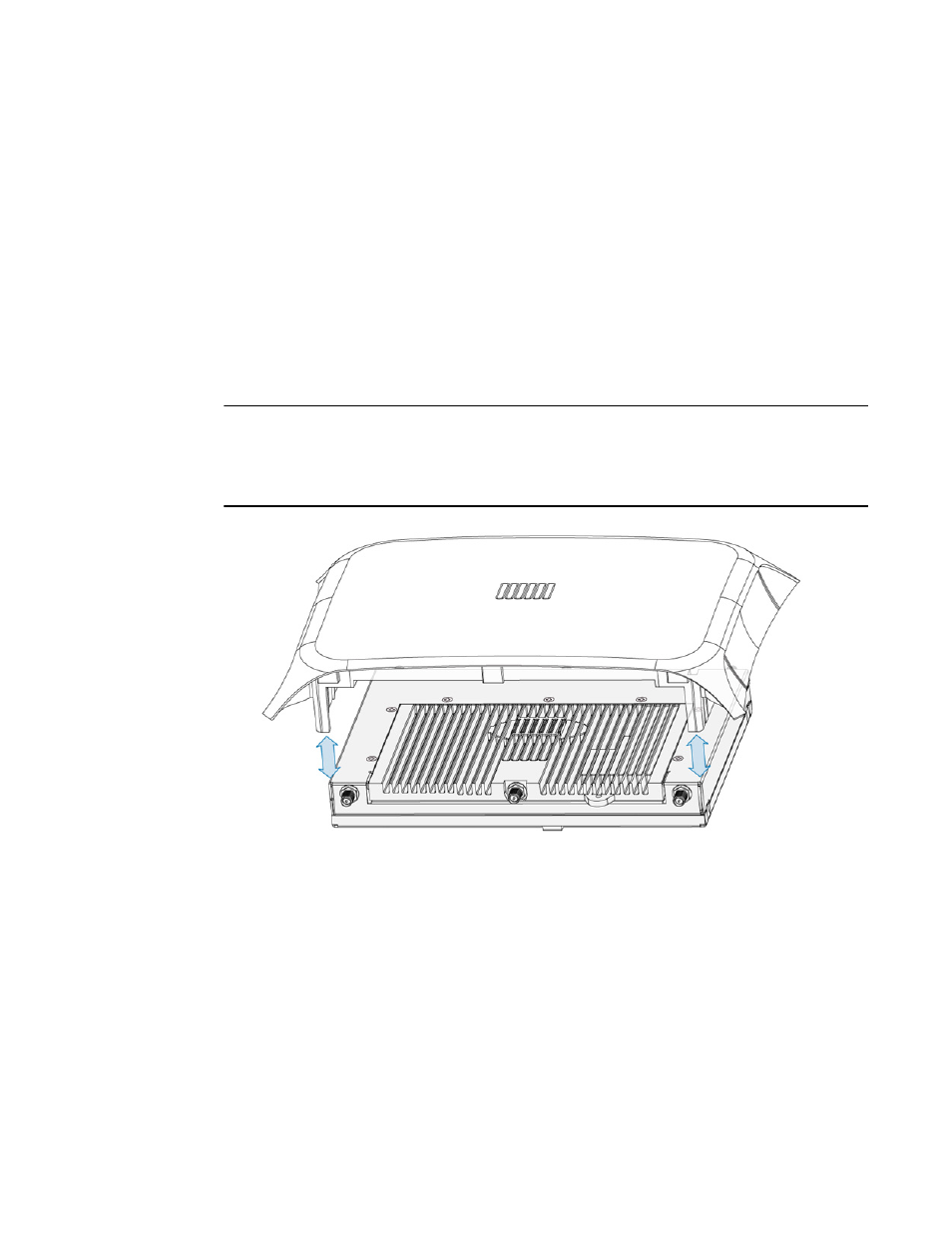
NOTE
The access point façade with 6 Element Antenna (Part No. ML-2452-PTA2M3X3-2) is separately
orderable and provides an integrated antenna option. The facade connects to the access point as
illustrated. Once attached, the LEDs continue to illuminate through the facade. Contact your
Brocade sales associate for information on ordering a facade with your access point.
Access point placement
For optimal performance, install the access point away from transformers, heavy-duty motors,
fluorescent lights, microwave ovens, refrigerators and other industrial equipment. Signal loss can
occur when metal, concrete, walls or floors block transmission. Install the access point in an open
area or add access points as needed to improve coverage.
Antenna coverage is analogous to lighting. Users might find an area lit from far away to be not
bright enough. An area lit sharply might minimize coverage and create dark areas. Uniform
antenna placement in an area (like even placement of a light bulb) provides even, efficient
coverage.
Place the access point using the following guidelines: