IAI America XSEL-S User Manual
Page 51
3. W
iring
45
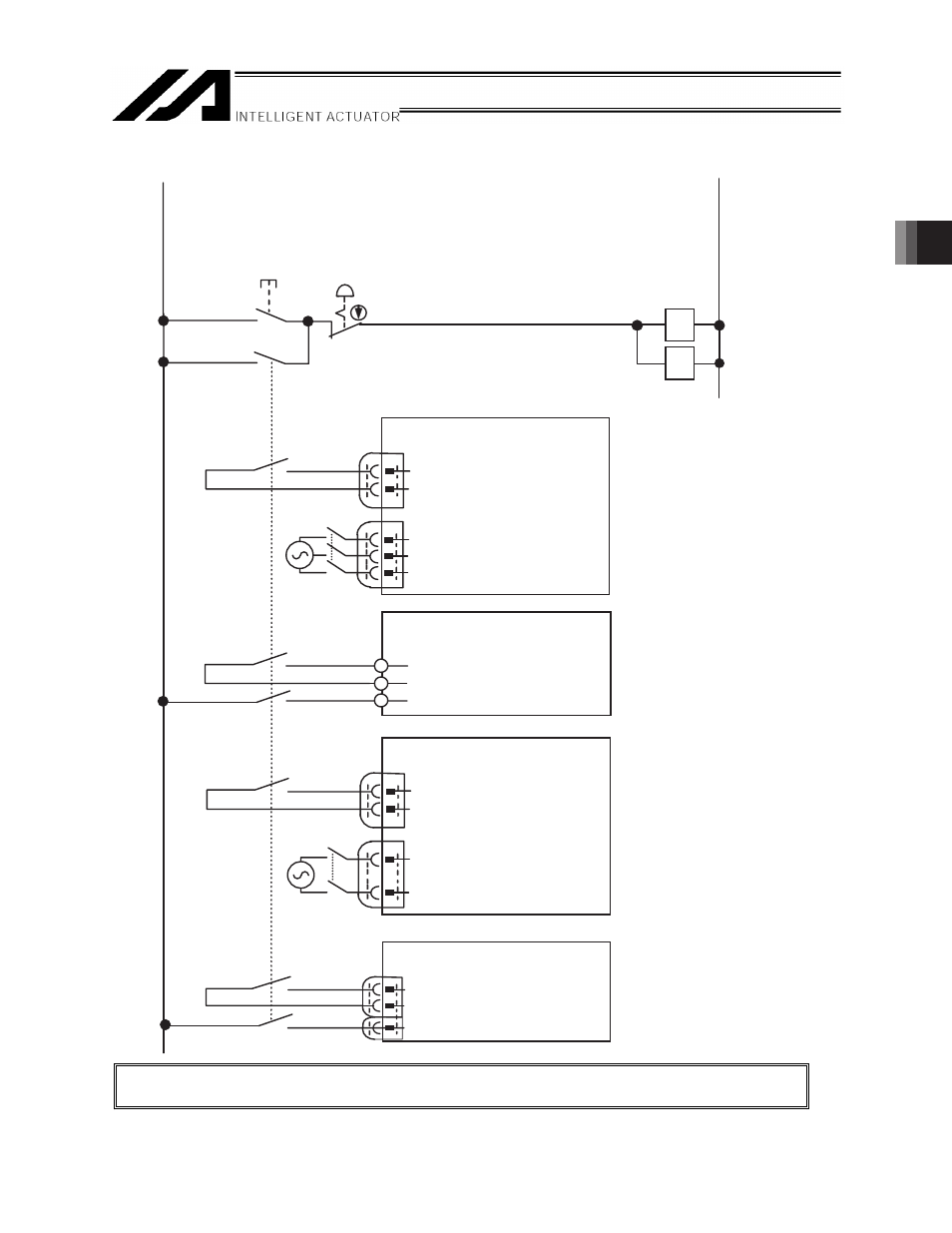
[2] Emergency stop system configuration example
x
To comply with the safety categories, make sure to follow the instructions in the instruction
manual of each controller for the emergency stop and driving source cutoff for each controller.
MC
Emergency
Stop Release
Switch
Emergency
Stop Switch
CR
CR
ACON-DV/PCON-DV
EMG-
MPI
MPO
MC
SCON-CA-DV/MSCON
R
MC
S
Drive Source
EMG+ (+24V)
EMG−
CR
X-SEL
R
MC
T
S Drive Source
Power Connector
Power Connector
EMGin (+24V)
EMGin (in)
CR
System I/O
System I/O
0V
24V
(Note 1)
CR
(Note 1)
(Note 1)
MC
MSEP-DV
MPI SLOT
MPO SLOT
EMG−
CR
(Note 1)
(Note 2)
(Note 2)
(Note 2)
(Note 2)
(Note1) Use the contact
capacity 0.2A or more.
(Note 2) The MC’s contact
capacity varies
depending on the
actuator to be
connected. Check it in
the instruction manual
for the main machine.