IAI America XSEL-S User Manual
Page 22
1.Outline of Control Method
16
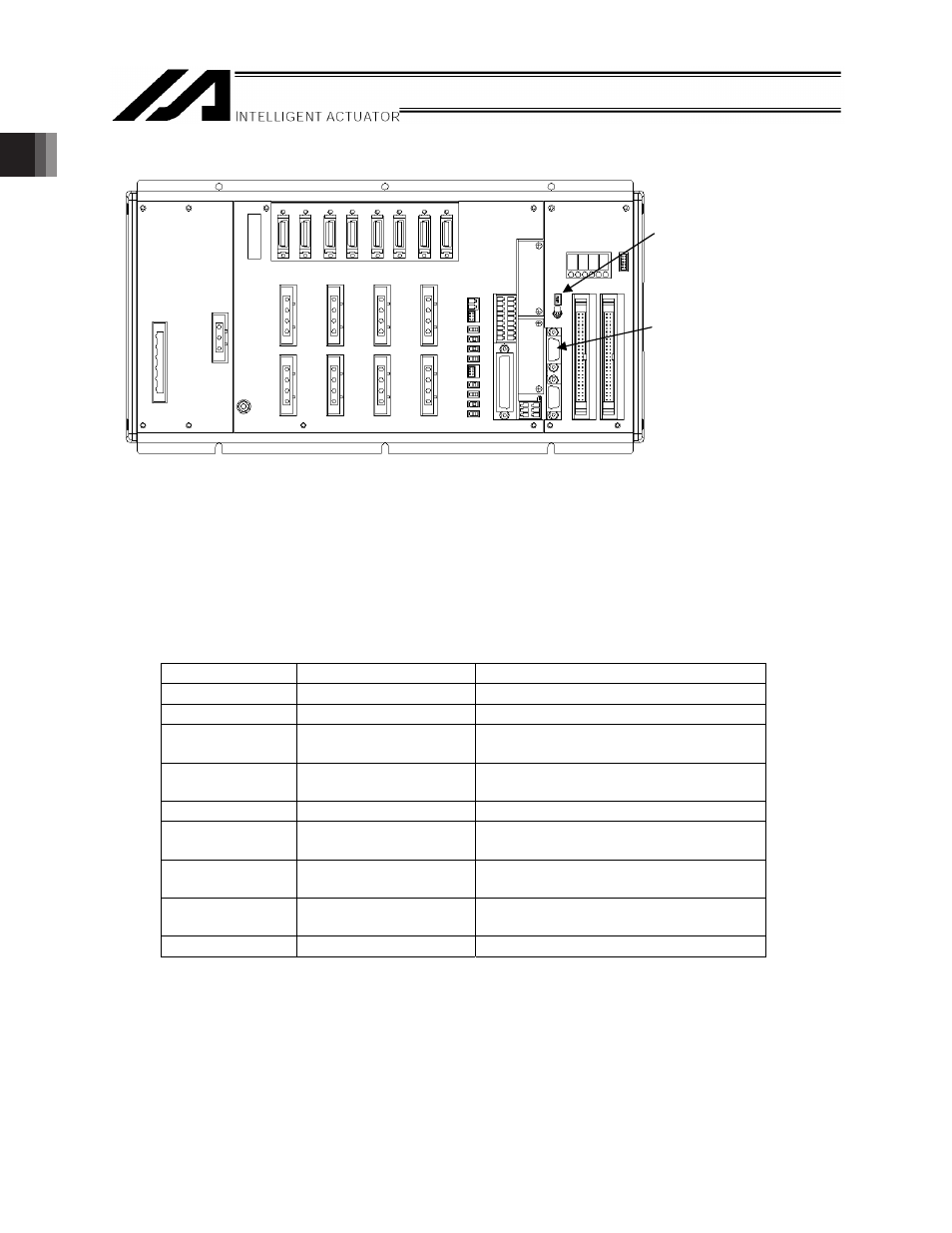
(2) XSEL-R/S/RX/SX/RXD/SXD
[1] System Operation Setting Switches
These are switches to set the operation mode of the system. (Normally, they are all OFF.)
When setting to RC Gateway Function, turn ON the switch No. 2
[2] RC gateway function connector [S2]
For SIO type, use the general-purposed RS232C Port Connector 2. Switch the setting over to RS485
communication with the system operation switches and connect directly to RC controller and
ROBONET.
Connector: D-sub, 9 pin (Controller side: Male, Cable Side: Female)
Pin number
Signal name
Details
1
(CD)
(Carrier Detection: Not used)
2
(RD)
(Receive Data (RXD): Not used)
(Note 1)
3
(SD)
Do not connect anything.
(Send Data (TXD): Not used)
4
(ER)
Do not connect anything.
(Equipment Ready (DTR): Not used)
5
SG
Signal Ground
6
(DR)
Do not connect anything.
Data Set Ready (DSR): Not used)
7
SA
Sent and received data A (Positive side)
(RS485)
8
SB
Sent and received data B (Negative side)
(RS485)
9
NC
Not used
Note 1 Short-circuit Pin 2 (RD) to the signal ground Pin 5 (SG).
[1] System Operation
Setting Switches
[2] RC gateway function
connector [S2]