IAI America XSEL-S User Manual
Page 47
3. W
iring
41
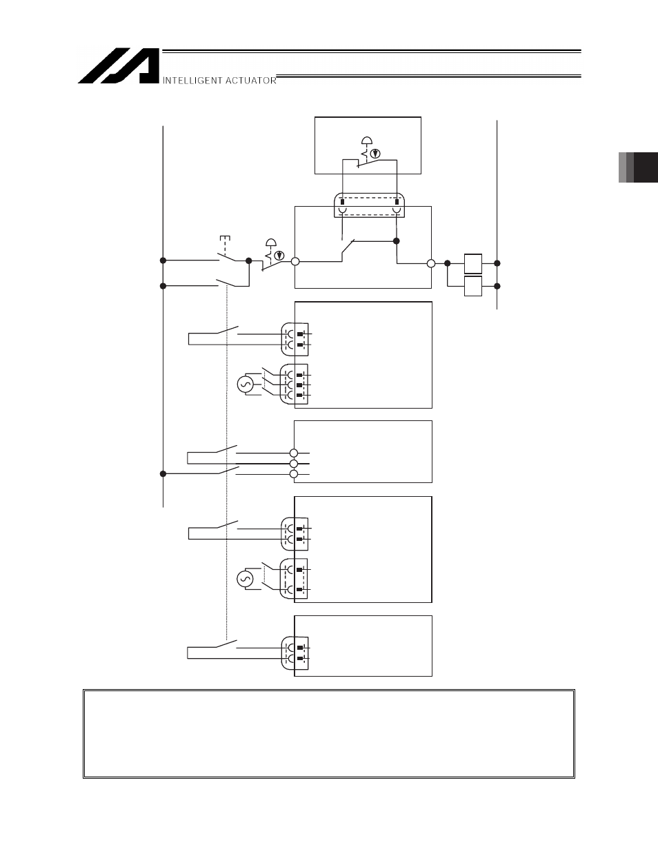
[6] Emergency stop system configuration example
24V
0V
Teaching pendant
EMG2
MC
Emergency
stop release
switch
PORT
switch
EMG1
Emergency
stop switch
CR
X-SEL
R
MC
T
S Drive Source
Power connector
EMGin ( +24V)
EMGin (in)
CR
System I/O
J1
ACON/PCON
EMG−
MPI
MPO
MC
EMG connector
EMG−
EMG+
CR
ROBONET
SCON/SCON-CA
R
MC
S
Drive Source
Power connector
EMG+ (+24V)
EMG −
CR
System I/O
CR
SIO
converter
(Note 1)
(Note 2)
CR
(Note 3)
(Note 2)
(Note 2)
(Note 2)
(Note 3)
x
EMG1 and 2 can be used to reflect the status of the emergency stop switch on the teaching
pendant in the emergency stop circuit of the system.
If a teaching pendant is used, turn the PORT switch to the ON side.
(This enables the emergency stop circuit of the teaching pendant.)
x
To comply with the safety categories, make sure to follow the instructions in the operation manual
of each controller for the emergency stop and driving source cutoff for each controller.
(Note1) The maximum flowing current
between EMG1 and EMG2 is
0.1A. Set the coil capacity to be
above it.
(Note2) Use the contact capacity 0.2A
or more.
(Note3) The contact capacity on MC
varies depending on the
connected actuator. See the
instruction manual for the main
unit.