1] a, Xsel-p/q/px/qx r/s/rx(d)/sx(d), Msep-dv – IAI America XSEL-S User Manual
Page 50: Mscon -dv, Pcon/acon/ scon-ca-dv
3. W
iring
44
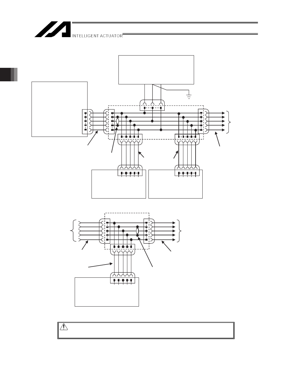
[1]-2 Connection diagram
Caution: Use a common 0V line for the 24V power supply for each controller.
(Except for SCON-CA)
[1] A
DC-N1-4R
1
2
3
4
5
1
2
3
4
5
1
2
3
4
5
1 2 3 4 5
1
3
5
1 2 3 4 5
1 2 3 4 5
1 2 3 4 5
[1] A
DCN1-2R
1
2
3
4
5
1 2 3 4 5
1 2 3 4 5
1
2
3
4
5
(Follow DeviceNet Standards for those
such as the decision of power capacity)
0V FG 24V
24V DC power supply
( Network power supply)
Class D grounding
(Formerly Class-III grounding)
(Note) Grounding should be only one
point in the network
T-junction tap
Communication
cable branch line
Communication cable main line
XSEL-P/Q/PX/QX
R/S/RX(D)/SX(D)
The connector of
RC Gateway Fieldbus board
V-(BK)
CAN_L (BL)
S
CAN_H(WT)
V+(RD)
Communication cable main line
Terminal Resistance 121Ω
MSEP-DV
DeviceNet
Communication
Connector
V
+(R
D
)
C
A
N
_H
S
C
A
N
_L
(B
L)
V
-(B
K)
(WT)
Communication
Connector
MSCON
-DV
DeviceNet
V
+(R
D
)
C
A
N
_H
(WT)
S
C
A
N
_L
(B
L)
V
-(B
K)
T-junction tap
When RC controller
is connected additionally
Communication cable main line
When no more RC controller is connected
(connect a terminal resistor 121Ω on the end of main line)
Communication
cable branch line
Communication cable main line
PCON/ACON/
SCON-CA-DV
DeviceNet
Communication
Connector
V
+(R
D
)
C
A
N
_H
S
C
A
N
_L
(B
L)
V
-(B
K)
(WT)