IAI America XSEL-S User Manual
Page 43
3. W
iring
37
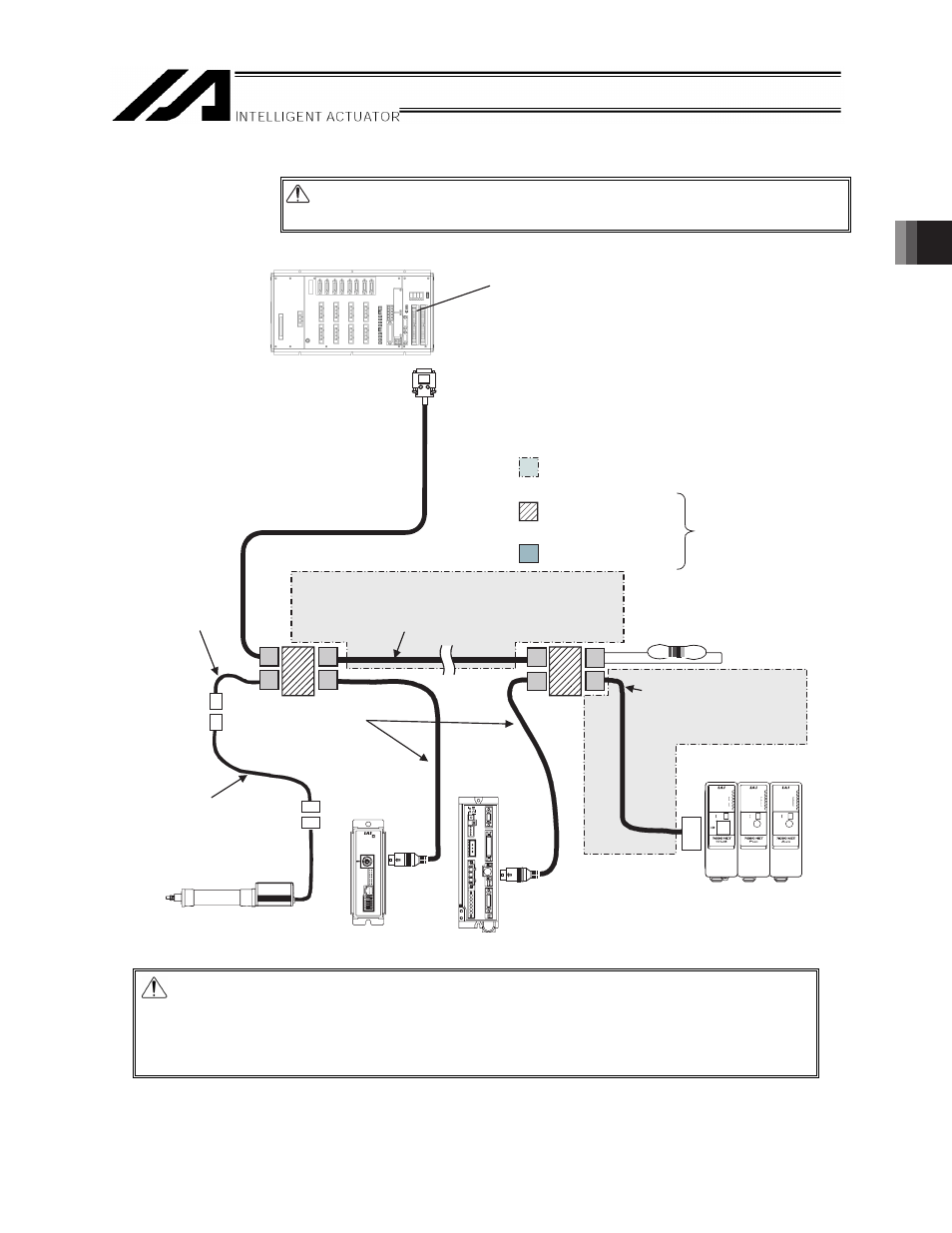
[4]-1 Wiring diagram (Example 4: When connecting to XSEL-R/S/RX/SX/RXD/SXD)
Caution: Use a common 0V line for the 24V power supply for each controller.
(Except for SCON)
XSEL-R/S/RX/SX/
RXD/SXD
ROBONET
SCON-C
PCON-SE
ACON-SE
ERC2-SE
Network
connection cable
CB-ERC2-CTL001
Power I/O Cable for SIO type
CB-ERC2-PWBIO-□□□
□□□ indicates the cable length.
Example: 050 = 5 m
Controller link cable
CB-RCB-CTL002
(Supplied with one each of
junction, e-CON connector
and 220Ω, 1/4W terminal resistor)
SV/ALM
SIO
PC
MOT
BK
MPO
24V
EMG-
MPC
RUN/ALM
EMG
T
C
1
0
ERROR
STATUS
MODE(AUTO)
MODE
MANU
AUTO
SIO
RDY/ALM
TX/RX
STATUS
3
2
1
0
BK(RLS)
BK
RLS
NOM
ADRS
RDY/ALM
TX/RX
STATUS
3
2
1
0
BK(RLS)
BK
RLS
NOM
ADRS
(Female) Connect to general-purpose
RS232C port connector 2.
Peripherals to be provided by the customer.
(Purchase all other components from IAI.)
Junction
(5-1473574-4 by AMP)
e-CON connector
(1473562-4 by AMP)
You can also
replace these with
a terminal block.
Recommended cable 1
(HK-SB/20276×L (m) 2P×AWG22
by Taiyo Cabletec Corporation)
To be provided by the customer.
Terminal resistor R = 220Ω
(Not required if a
ROBONET is connected.)
Recommended cable 2
To be provided by the
customer according to the
connection diagram shown
in 3.2.1 [4]-2.
Turn ON only No. 2 in the system operation setting switches
[Keep the others turned OFF]
SIO Port RC Gateway
Communication Cable
□□□ indicates the cable length.
Example: 005 = 0.5 m
Caution: Ɣ Multiple ROBONET GatewayR_SIO units cannot be connected to a single
network.
Ɣ Since the ROBONET has a built-in terminal resistor, connect the ROBONET to
the junction farthest away from the X-SEL (at the end of the trunk line).
Do not connect a terminal resistor to the junction.