IAI America XSEL-S User Manual
Page 135
6.
Appendix
129
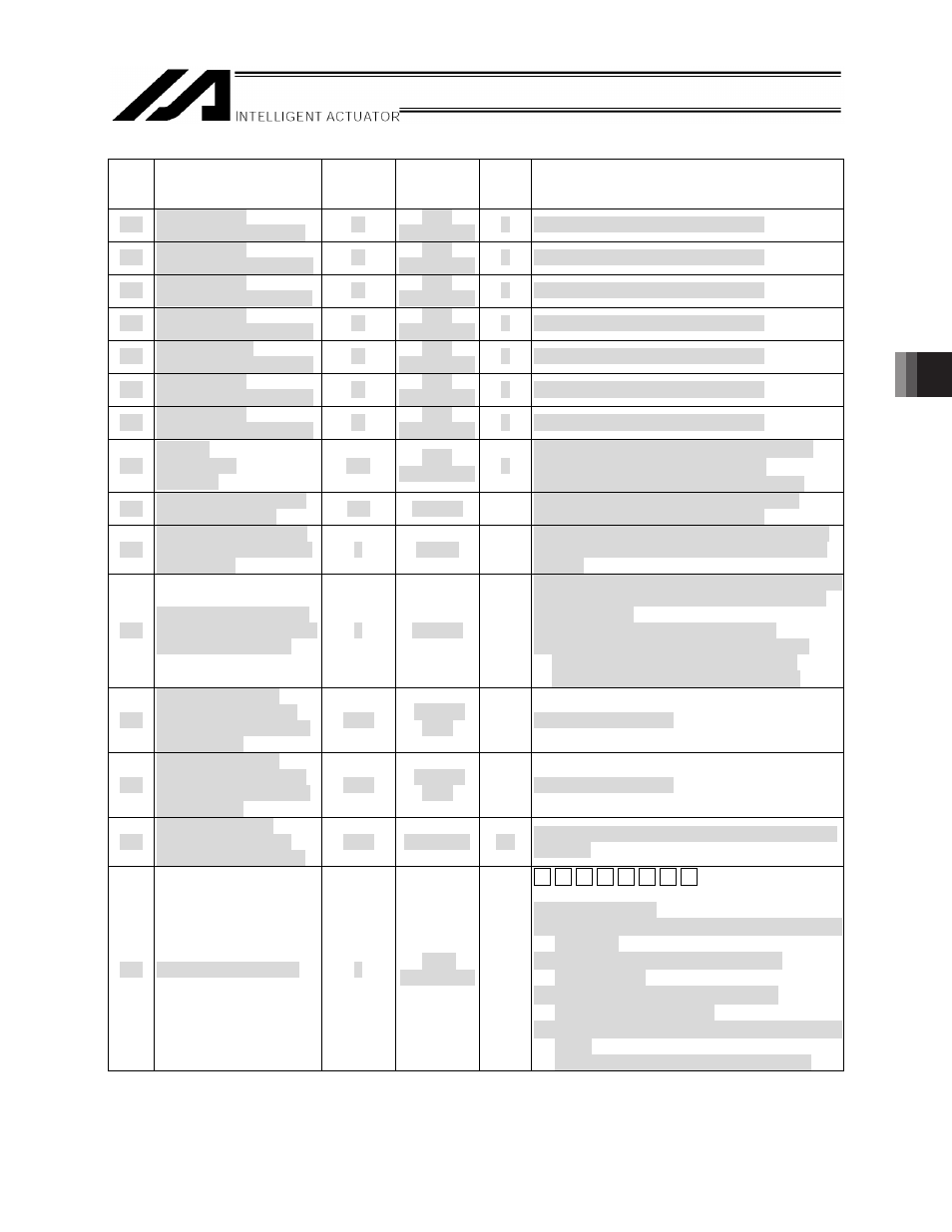
I/O parameters (The shaded parameters in bold are new parameters: Continued)
No.
Parameter name
Default
value
(reference)
Input range
Unit
Remarks
441 Fieldbus slave
9 Composition definition
0
H
0
H
to
FFFFFFFF
H
F
(I/O Parameter Equivalent to No.432)
442 Fieldbus slave
10 Composition definition
0
H
0
H
to
FFFFFFFF
H
F
(I/O Parameter Equivalent to No.432)
443 Fieldbus slave
11 Composition definition
0
H
0
H
to
FFFFFFFF
H
F
(I/O Parameter Equivalent to No.432)
444 Fieldbus slave
12 Composition definition
0
H
0
H
to
FFFFFFFF
H
F
(I/O Parameter Equivalent to No.432)
445 Fieldbus slave
13 Composition definition
0
H
0
H
to
FFFFFFFF
H
F
(I/O Parameter Equivalent to No.432)
446 Fieldbus slave
14 Composition definition
0
H
0
H
to
FFFFFFFF
H
F
(I/O Parameter Equivalent to No.432)
447 Fieldbus slave
15 Composition definition
0
H
0
H
to
FFFFFFFF
H
F
(I/O Parameter Equivalent to No.432)
448
Fieldbus
configuration
attribute 1
4B
H
0
H
to
FFFFFFFF
H
F
Bits 0-11
㧦
EPR (Expected Packet Rate)
Bits 12-19 㧦 ISD (Interscan Delay)
* Perform the setting to make ISD*3 < EPR.
501 Number of RC gateway
position data points
128
0 to 512
Number of position data points used in the
Method to use position data in X-SEL
502
Largest axis number for
definition of RC gateway
position data
0
0 to 15
Largest axis number used for allocating the RC
axis position data area in the user-data backup
memory
503
Number of position data
points for definition of RC
gateway position data
0
0 to 512
Number of position data points used for allocating
the RC axis position data area in the user-data
backup memory
* If “0” is set, the area is not allocated.
* If a value other than “0” is set, the area is
allocated regardless of whether the RC
gateway function is enabled or disabled.
504
Port number of first
occupied/shared input
port in RC gateway PLC
through mode
1000
1000 to
3999
1000 + (multiple of 16)
505
Port number of first
occupied/shared output
port in RC gateway PLC
through mode
4000
4000 to
6999
4000 + (multiple of 16)
506
Timeout period for
connection of RC PC
software to RC gateway
3000
0 to 99999
ms
Set the connection timeout period for the RC PC
software.
507 RC gateway attribute 1
0
0
H
to
FFFFFFFF
H
[8] [7] [6] [5] [4] [3] [2] [1]
H
m
Enter as HEX
values of 0 to F.
Set [8] to [5] to “0.”
[4] Bits 12 to 15㧦Time to wait for link in initializing
(5 to F [s])
[3] Bits 8 to 11㧦Data refresh delay time
(0 to F [10ms])
[2] Bits 4 to 7㧦Data refresh check time
(3 to F [Number of times])
[1] Bits 0 to 3㧦Emergency stop non-conformance
check
(0: Have a check, 1: Not to have a check)