1 wiring method of sio type, W iring 29 – IAI America XSEL-S User Manual
Page 35
3. W
iring
29
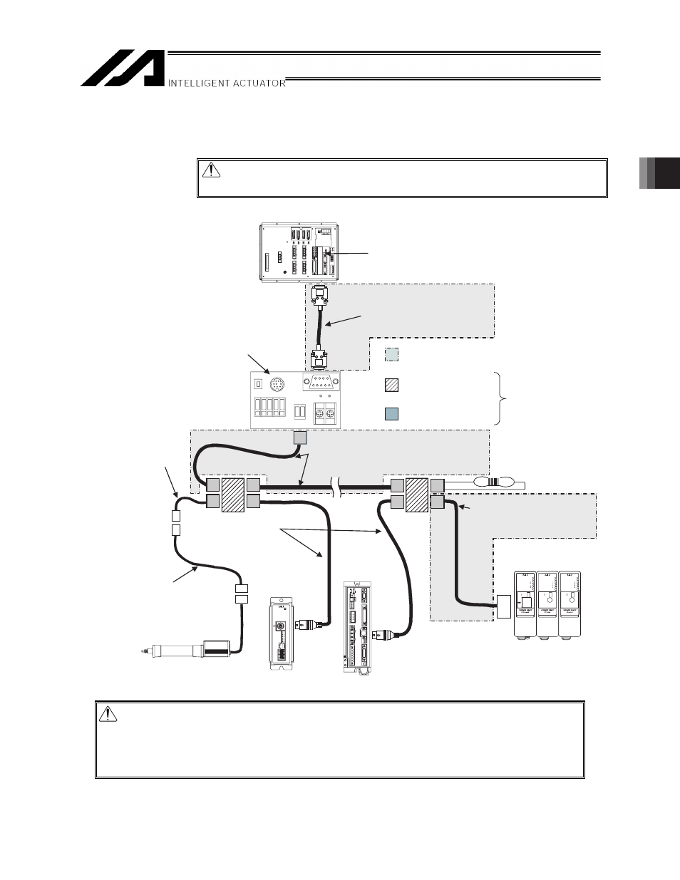
3.2.1 Wiring Method of SIO type
[1]-1 Wiring diagram (Example 1: When SIO converter is used for XSEL-P/Q/PX/QX)
RUN/ALM
EMG
T
C
1
0
ERROR
STATUS
MODE(AUTO)
MODE
MANU
AUTO
SIO
RDY/ALM
TX/RX
STATUS
3
2
1
0
BK(RLS)
BK
RLS
NOM
ADRS
RDY/ALM
TX/RX
STATUS
3
2
1
0
BK(RLS)
BK
RLS
NOM
ADRS
SV/ALM
SIO
PC
MOT
BK
MPO
24V
EMG-
MPC
XSEL-P/Q/PX/QX
ROBONET
SCON-C
PCON-SE
ACON-SE
ERC2-SE
SIO converter
RCB-TU-SIO
(RS232C
⇔
RS485)
(With built-in 220Ω
terminal resistor)
Network
connection cable
CB-ERC2-CTL001
Controller link cable
CB-RCB-CTL002
(Supplied with one each of
junction, e-CON connector and
220Ω, 1/4W terminal resistor)
IAI’ s teaching pendant or PC software can be connected.
Note, however, that the teaching pendant/PC software
cannot be connected simultaneously with the X-SEL
controller.
If the two are connected at the same time, proper
communication cannot be performed and errors will
generate. (Turn OFF the X-SEL controller power while the
teaching pendant/PC software is in use).
Set the +5V supply switch to the left position.
(5V cannot be output)
(Female) Connect to general-purpose
RS232C port connector S2.
RS232C cross cable
To be provided by the customer
(commercial product).
(Female)
Peripherals to be provided by the customer.
(Purchase all other components from IAI.)
Junction
(5-1473574-4 by AMP)
e-CON connector
(1473562-4 by AMP)
You can also
replace these with a
terminal block.
Terminal resistor R = 220Ω
(Not required if a
ROBONET is connected.)
Recommended cable 1
(HK-SB/20276×L (m) 2P×AWG22
by Taiyo Cabletec Corporation)
To be provided by the customer.
Recommended cable 2
To be provided by the customer
according to the connection
diagram shown in 3.2.1 [1]-2.
Power I/O Cable for SIO type
CB-ERC2-PWBIO-□□□
□□□ indicates the cable length.
Example: 050 = 5 m
TB1
J4
J5
TB2
A
LE
D1
TB1
B
LE
D2
RS
232
PO
RT
ON
EM
G
1
EM
G
2
24
V
0V
FG
Caution: Use a common 0V line for the 24V power supply for each controller.
(Except for SCON)
Caution: Ɣ Multiple ROBONET GatewayR_SIO units cannot be connected to a single
network.
Ɣ Since the ROBONET has a built-in terminal resistor, connect the ROBONET to
the junction farthest away from the X-SEL (at the end of the trunk line).
Do not connect a terminal resistor to the junction.