IAI America XSEL-S User Manual
Page 46
3. W
iring
40
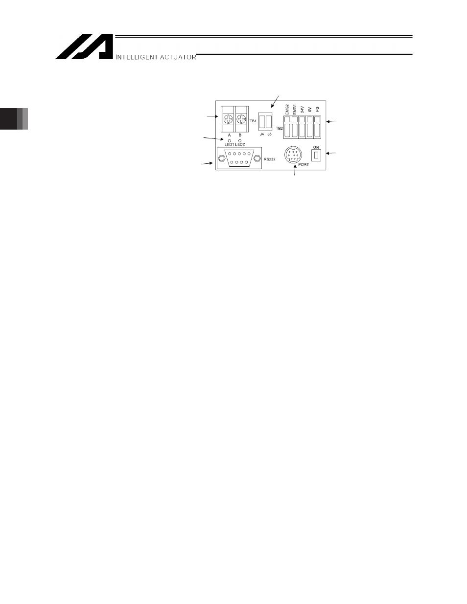
[5] SIO converter for X-SEL and RC controller connection (RCB-TU-SIO)
This is a RS232C RS485 converter.
1) D-sub, 9-pin connector
This connector provides connection points with the host.
Connect to general-purpose RS232C port connector 2 (S2) on the X-SEL controller using a RS232C
cross cable (commercial product).
2) Monitor LEDs (LED1, LED2)
x
LED1 : This LED turns ON/blinks while the RC controller is sending data.
x
LED2 : This LED turns ON/blinks while the host is sending data.
3) Link-connection terminal block (TB1)
This terminal block provides connection points for linking RC controllers.
x
A : Connect to pin 1 on the RC controller’s communication connector (SGA).
x
B : Connect to pin 2 on the RC controller’s communication connector (SGB).
4) Link connectors (J4, J5)
These connectors provide connection points with the RC controller.
An optional link cable (CB-RCB-CLT002) can be connected directly.
5) Power-supply & emergency-stop terminal block (TB2)
x
EMG1, EMG2
: Contact outputs for the emergency stop switch on the teaching pendant
When the PORT switch is in the ON position, EMG1 and EMG2 are connected
to the emergency stop switch on the teaching pendant. When the PORT switch
is in the OFF position, EMG1 and EMG2 are shorted.
x
24V
: Supply +24V power. (Current consumption: 0.1 A or less)
x
0V
: Supply 0V power. (Use a common 0V line for 24V DC controllers.)
x
FG
: A FG connection terminal.
* Applicable wires Single wire
I
0.8 to 1.2 mm
Stranded wire
AWG18 to 20 (stripped by 10 mm, with wire tips soldered)
6) PORT switch
x
ON
: When a teaching pendant is used
x
OFF : When no teaching pendant is used
7) Mini-DIN, 8-pin connector
This connector provides connection points with the teaching pendant or PC software.
This connector can be used when no X-SEL controller is connected or a X-SEL controller is connected
but its power is turned OFF.
[4] Link connector (J4, J5)
[5] Power-supply
emergency-stop
terminal block (TB2)
[6] PORT switch
[3] Link-connection terminal block (TB1)
[2] Monitor LEDs (LED1, LED2)
[1] D-sub, 9-pin connector
[7] Mini-DIN, 8-pin connector