IAI America XSEL-S User Manual
Page 37
3. W
iring
31
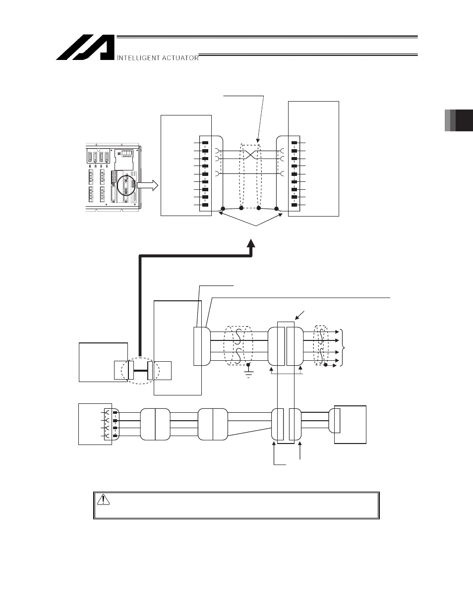
[1]-2 Connection diagram (Example 1: When SIO converter is used for XSEL-P/Q/PX/QX)
RS232C cable (cross)
XSEL
CD
RD
SD
ER
SG
DR
RS
CS
+5V
1
2
3
4
5
6
7
8
9
1
2
3
4
5
6
7
8
9
2
3
5
2
3
5
NC
RD
SD
NC
SG
NC
NC
NC
NC
RCB-TU-SIO
HK-SB/20276×L
2P×AWG22
J3
SGA
SGB
+5V
GND
1
2
3
4
1
2
3
4
1
2
3
1
2
3
1
2
3
1
2
7
4
1
2
4
1
2
3
4
OR
BL
BR
GN
OR
BL
BR
GN
OR
BL
GN
YW
OR
BL
ERC2-SE
CB-ERC2-PWBIO
CB-ERC2-CTL001
PCON-SE, ACON-SE
CB-RCB-CTL002
1
2
3
4
1
2
3
4
1
2
3
4
Cable length: Not longer than 10 m
(commercial product)
General-purpose
RS232C port
connector 2
SIO converter
RCB-TU-SIO
J3 (D-sub, 9-pin)
D-sub connector (9P Female)
J4 or J5
e-CON connector (4-1473562-4 by AMP) / Housing color: Green
Recommended cable 1
Recommended: Taiyo
Cabletec Corporation
4-way junction
(5-1473574-4 by AMP)
To [1] (next page)
e-CON connector
(4-1473562-4 by AMP)
Housing color: Green
Controller link cable
Network connection cable
SIO converter
XSEL
General-purpose
RS232C port
connector 2
Power I/O Cable for SIO type
Nth controller (N = Maximum 16)
e-CON connector (3-1473562-4 by AMP)
Housing color: Orange
Caution: Use a common 0V line for the 24V power supply for each controller.
(Except for SCON)