IAI America XSEL-S User Manual
Page 21
1. Outline of Control Method
15
1.3
Name and Function of Each Part Relating to RC Gateway Function
1.3.1 For SIO type
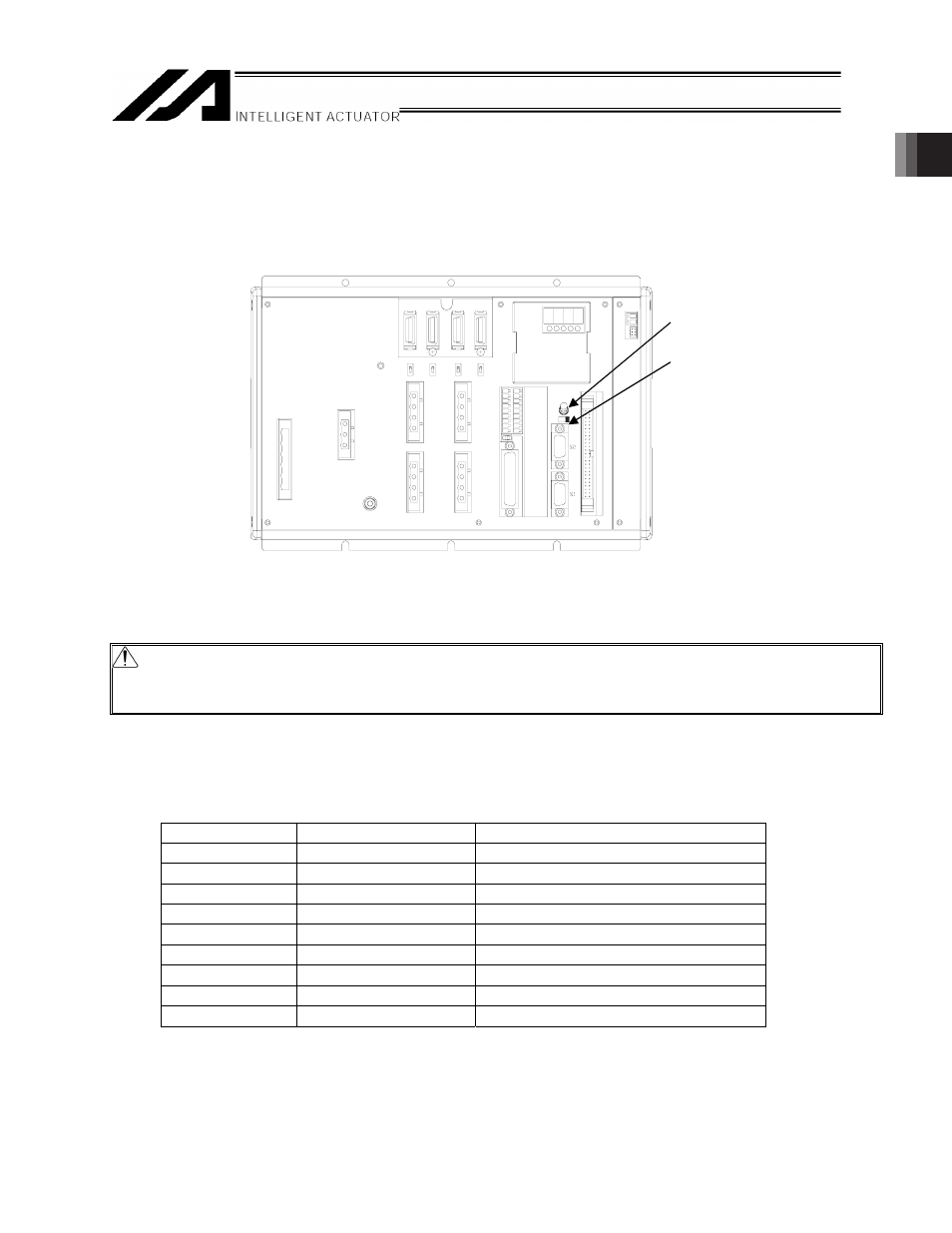
(1) XSEL-P/Q/PX/QX
[1] +5V supply switch
If a SIO converter is used, set this switch to the left position. (+5V will not be output.)
If a RS232C converter unit (RCB-CV-GW) is used, set the switch to the right position. (+5V will be
output.)
Caution: If the port is used as a standard RS232C port, be sure to set this switch to the left position (so
that +5V will not be output). Failure to do so may cause shorting of the +5V power output circuit
depending on how the connection cable is wired.
[2] RC gateway function connector [S2]
For SIO type, use the general-purposed RS232C Port Connector 2.
Connect to RC Controller and ROBONET using SIO Converter.
Connector
: D-sub, 9-pin (Controller: Male end / Cable: Female end)
Interface standard : RS232C
Pin number
Signal name
Details
1
CD
Carrier Detection (not used)
2
RD
Receive Data
3
SD
Send Data
4
ER
Equipment Ready
5
SG
Signal Ground
6
DR
Data Set Ready
7
RS
Request to Send
8
CS
Clear to Send
9
+5V
RCB-CV-GW Converter Power
[1] +5V supply switch
[2] RC gateway function
connector [S2]