IAI America XSEL-S User Manual
Page 41
3. W
iring
35
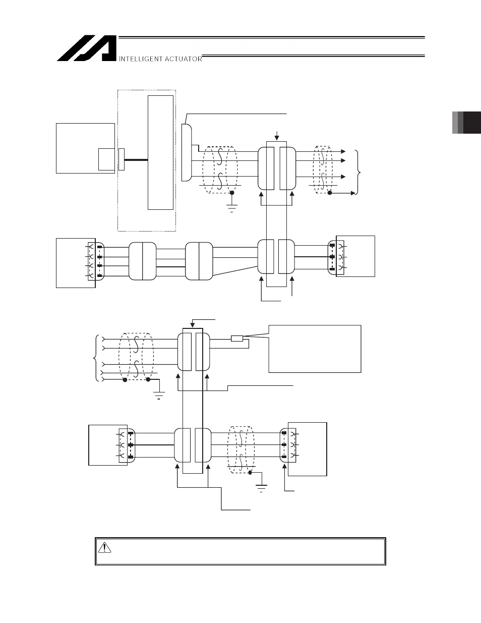
[2]-2 Circuit diagram (Example 2: When RS232 conversion unit is used for XSEL-P/Q/PX/QX)
CB-RCB-SIO
[1] A
(4-1473562-4 by AMP)
CB-ERC2-CTL001
CB-RCB-CTL002
RCB-CV-GW
ERC2-SE
SGA
SGB
+5V
GND
1
2
3
4
1
2
3
4
1
2
3
4
1
2
3
1
2
3
1
2
3
1
2
7
4
1
2
4
OR
BL
BR
GN
OR
BL
BR
GN
OR
BL
GN
YW
OR
BL
2
4
1
2
3
1
2
3
5
SGA
SGB
GND
CB-ERC2-PWBIO
PCON-SE, ACON-SE
HK-SB/20276×
2P×AWG22
HK-SB/20276×L
2P×AWG22
ROBONET_GatewayR_SIO
SCON-C
SGA
SGB
GND
SA
SB
SG
MC1.5/4-ST-3.5
[1] A
1
2
1
2
3
1
2
7
1
2
3
1
2
3
RJ11 connector (modular jack)
Communication cable
4-way junction
(5-1473574-4 by AMP)
e-CON connector
Housing color: Green
Controller link cable
Network connection cable
XSEL
general-purpose
RS232C port
connector 2
RS232
conversion unit
Power I/O Cable for SIO type
Recommended cable 1
Recommended: Taiyo
Cabletec Corporation
4-way junction (5-1473574-4 by AMP)
Nth controller (N = Maximum 16)
e-CON connector (3-1473562-4 by AMP)
Housing color: Orange
Terminal resistor R = 220
Ω
(Supplied with the controller
link cable)
Not required if a ROBONET
is connected.
e-CON connector
Housing color: Green
(4-1473562-4 by AMP)
Recommended cable 2
Recommended: Taiyo
Cabletec Corporation
(Supplied)
e-CON connector
(3-1473562-4 by AMP)
Housing color: Orange
Nth controller (N = Maximum 16)
Caution: Use a common 0V line for the 24V power supply for each controller.
(Except for SCON)