Wiring, 1 notes on wiring – IAI America XSEL-S User Manual
Page 33
3. W
iring
27
3.
Wiring
3.1
Notes on Wiring
[1] Provide noise elimination measures for the electrical devices located along the same power-supply
path or in the same system according to the operation manuals for the X-SEL controller, RC controller
and ROBONET.
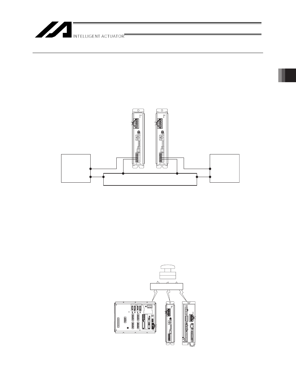
[2] If multiple power-supply units are used to supply 24V DC power to RC controllers, connect the 0V
lines of the power supplies for respective controllers.
[3] Be sure to shield the communication cable. Connect the cable’s shield to a single point ground.
[4] Make sure emergency stop signals are input simultaneously to the X-SEL and each RC controller
/ROBONET. If the emergency stop timing of the X-SEL varies from that of the RC controller/ROBONET
by a specified time (approx. 5 seconds) or longer, the X-SEL will generate an error “6B4: RC gateway
emergency stop inconsistency error”
(Note 1)
and enter the emergency stop mode (cold-start level).
Note1 Ɣ Connecting some ERC2 controllers or avoiding this error detection on other controllers, set
bits 0 to 3 of the X-SEL controller’s I/O parameter No. 507 to “1.”
(The setting of I/O Parameter No. 507 is available in V0.90 or later for X-SEL P/Q and
V0.42 or later for X-SEL PX/QX. Refer to 6.1 for details.)
Ɣ If the RC controller is connected via the X-SEL, this error will not occur.
Emergency stop ON!
0V common)
+
−
Power
supply 1
Power
supply 2
+
−
(