0 system status display, 1 introduction, 0 - system status display – Micromod Micro-PWC: 53PW6000 MicroPWC Configuration Guide User Manual
Page 279: Figure 8-1. system status display, Figure 8-2. ssd object for a micro-pwc, Section 8
Micro-PWC CONFIGURATION GUIDE
System Status Display 259
8.0 System Status Display
8.1 Introduction
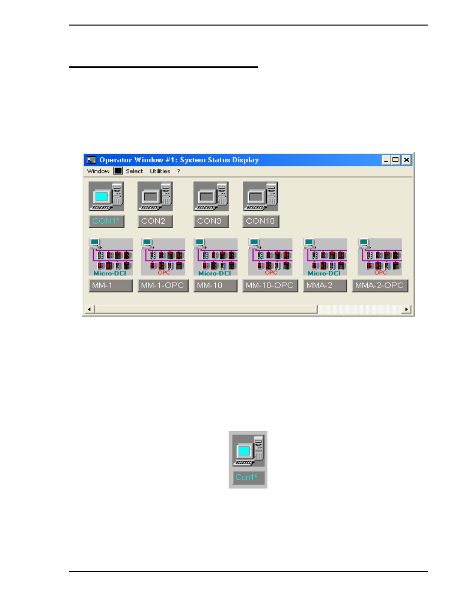
The System Status Display (SSD), an example of which is shown in
, provides information about
each node connected to the Ethernet network. A node can be a Micro-PWC console application or a Micro-
DCI communications program. Micro-PWCs on the network are labelled as Con.
Each node on the network is depicted by a pictorial representation known as an SSD object.
An SSD object is composed of a schematic illustration of the node above a button containing the name of
the node and information on the state of the node and its connections to the network. The appearance of
the SSD object varies, depending on the type and state of the node. Click the button to access a menu for
the node represented by the SSD object. Like the appearance of the SSD object, the entries on the menu
vary with the type of node represented.
provides an example of the SSD object for a
Micro-PWC.
The System Status Display is organized into rows of nodes, using the following rules:
1.
A row contains nodes of only one type of device (e.g., Micro-PWC consoles).
Figure 8-1. System Status Display
TC00535A
Figure 8-2. SSD Object for a Micro-PWC