11 the spin attribute, 12 combining attributes, 2 configuring submodels – Micromod Micro-PWC: 53PW6000 MicroPWC Configuration Guide User Manual
Page 151: Figure 4-14. spin configuration window, Section, Section 4.3.2, configuring submodels, For det
Micro-PWC CONFIGURATION GUIDE
Grafx Editor 131
4.3.1.2.11 The SPIN Attribute
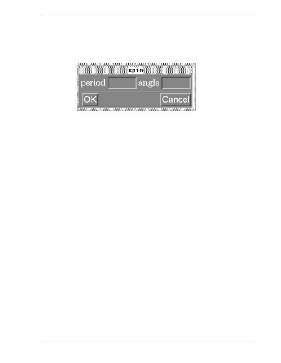
The Spin attribute causes an object to be rotated about its reference point in periodic increments, for as
long as the expression is true. Click within the Spin attribute box to select the attribute. The Spin Configu-
ration window (
) will appear.
Figure 4-14. Spin Configuration Window
Use the Spin Configuration window to enter values for the following parameters:
•
Period
•
Angle
As in the Blink attribute, the Period parameter for the Spin attribute is measured in tenths of a second. The
number entered for this parameter defines the length of time it will take (in tenths of a second) for the
object to be moved the number of degrees specified in the Angle parameter. The minimum value for the
Spin Period is 3 (tenths of a second), the default is 5 (one half second).
The number entered in the Angle parameter entry box specifies the number of degrees the object will turn
per period. A positive number results in counterclockwise movement, while a negative number causes
clockwise movement. When the expression is false, the object returns to its original position.
4.3.1.2.12 Combining Attributes
Note that when either the Blink or Spin attribute is selected, all other attributes are stippled out and made
unavailable. It is possible to combine the Blink and Spin attributes with the other dynamic attributes and
with each other by using multiple expressions, and creating a separate expression each for the Blink
attribute, the Spin attribute and all other attributes. Avoid configuring two different sets of Blink (or Spin)
dynamics (for the same object) which could be true simultaneously, as this can cause unpredictable
results.
4.3.2 Configuring Submodels
A submodel may already contain internal dynamics, configured by MicroMod Automation or by the user
during an earlier configuration session. (This can be done via the Expression Dynamics window discussed
above, by either creating a variable name in the Expression entry box, or if a variable was entered in an
attribute setting box, instead of a value. See Example 3 in
Section 4.3.4, Dynamic Configuration Exam-
The Submodel Configuration window (an example is shown in
) is used to assign values (which
can be in the form of controller database points) to dynamic variables.
Use one of the following methods to display this window:
✎ Note
The spin feature is already incorporated in the dynamic submodels
FP_DYwheel, FP_DYpump_rt and FP_DYpump_lf, which are
supplied by MicroMod Automation.