1 the zoom operations - in, out, fit, pick, Table 4-1. view size information – Micromod Micro-PWC: 53PW6000 MicroPWC Configuration Guide User Manual
Page 103
Micro-PWC CONFIGURATION GUIDE
Grafx Editor 83
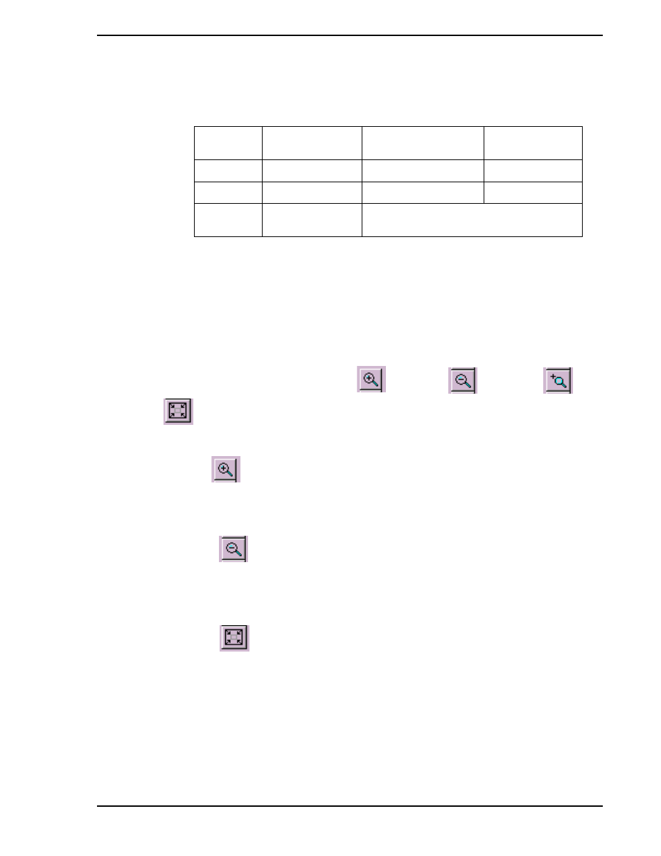
Coordinates for the minimum, maximum and default view sizes are shown in
.
4.2.1.10.1 The Zoom Operations - In, Out, Fit, Pick
The Zoom operations change the view size of the Working View portion of a child window, but do not
change the model which is being edited. These operations are performed using the
following buttons found on the View toolbar: Zoom In
,
Zoom Out
,
Zoom Pick
, and
Zoom To Fit
.
These options can also be accessed via the Grafx menus by selecting the menu seqence View > Zoom.
Each time the Zoom In
button is clicked, the view size is reduced by 62%. The center of the view
remains unchanged. Objects in the model which are visible appear correspondingly larger, but are not
actually modified; remember that this operation merely magnifies a portion of the graphic for the conve-
nience of the configurer. If the view has been fully zoomed in, no further change occurs to the view size.
Each time the Zoom Out
button is clicked, the view size is enlarged by 62%. The center of the view
remains unchanged. Objects in the model which are visible appear correspondingly smaller, but are not
actually modified; this operation simply allows the entire graphic to be displayed in the Working View for
the convenience of the configurer. If the view has been fully zoomed out, no further change occurs to the
view size.
Click on the Zoom To Fit
button to adjust the view size by automatically "zooming out" or "zooming
in" so that the entire model is visible and fills the Working View. If there are no objects outside the default
view size (100 units by 75 units), the view size will not change (i.e., the view will not "zoom in" in order to
make the objects present fill the Working View). When a model is initially loaded into the Working View, a
Zoom To Fit operation is automatically performed. (This is also done when an installed graphic is dis-
played in an Operator Window.)
The dimensions of the default view size are enclosed in a rectangle composed of solid lines. When zoom-
ing or panning outside the default view dimensions, this rectangle or portions thereof may be visible within
Table 4-1. View Size Information
VIEW SIZE
NUMBER of
UNITS
LOWER LEFT
COORDINATE
UPPER RIGHT
COORDINATE
Default
100 x 75
0, 0
100, 75
Maximum
400 x 300
-150, -112.5
250, 187.5
Minimum
20 x 15
Can be located anywhere within the Maximum
view size coordinates.
✎ Note
The use of Grid Mode (
Section 4.2.5.1.8, Setting the Grid
) is unaffected by Zoom and Pan operations.