RISCO Group LightSYS 2 User Manual
Page 47
Installing Bus Devices
Page 47
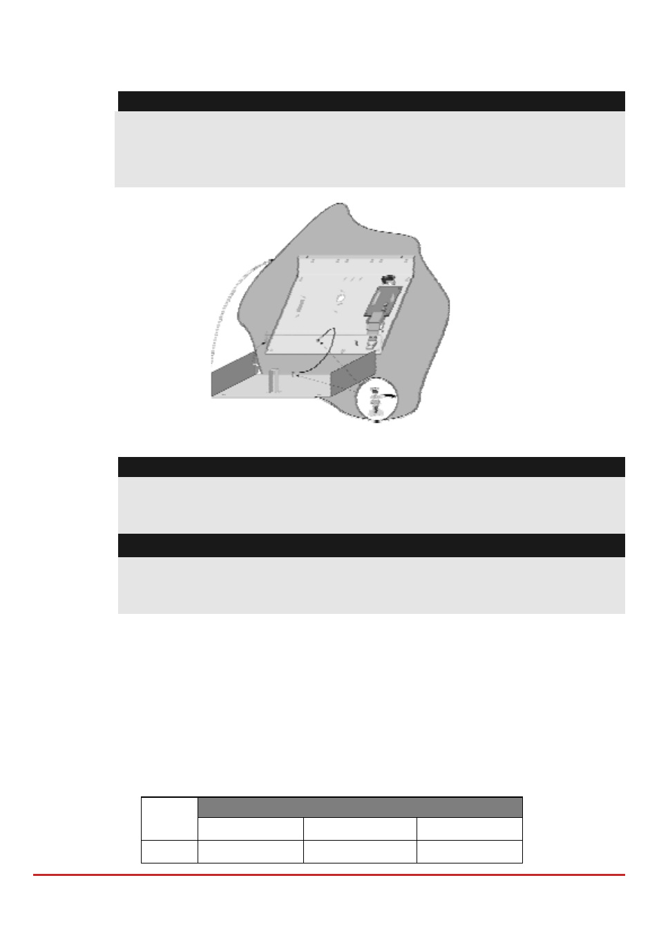
To mount the 3A Switching Mode Power Supply (SMPS)
1. Mount the SMPS and the backup battery inside a metal box.
Important:
The SMPS should be serviced by qualified personnel only!
Unless serviced, the SMPS box must be closed with screws at all times!
Use only safety‐approved wires in accordance with the national rules.
The SMPS is designed for indoor use only!
Figure 3-10: SMPS Inside a Metal Box
Note:
Prior to installation, calculate the total current consumption of the connected
devices in order not to exceed the power supply’s maximum current
consumption!
Important:
To prevent risk of electric shock, disconnect all power sources before servicing!
Under no circumstances should mains be connected to the PCB other than to the
main terminal block!
2. Locate the SMPS metal box in a clean and dry location, close to the mains.
3. Open the SMPS box by releasing the attaching screws.
4. When attaching the box to the wall, it is recommended to use Ø4.2mm, 32mm
length screws (DIN 7981 4.2X32 ZP)
5. Connect the incoming mains cable to the main fuse terminal block.
6. Wire the SMPS terminals as follows:
a. Connect the bus Terminals: Connect only three of the first four terminals at
the left of the Power Supply expansion module to the main panelʹs 4‐wire
bus, as follows
Expansion Bus Terminals
COM
BUS
BUS
Color
BLK (Black)
YEL (Yellow)
GRN (Green)