RISCO Group LightSYS 2 User Manual
Page 29
Mounting and Wiring
Page 29
Wiring Auxiliary Devices
Use the Auxiliary Power AUX (+) COM (‐) terminals to power PIRs, glass‐break detectors
(4‐wire types), smoke detectors, audio switches, photoelectric systems and/or any device
that requires a 12V DC power supply.
Notes:
If the auxiliary outputs are overloaded (exceed 800mA) and are shut down, you must
disconnect all loads from the outputs for a period of at least 10 seconds before you
reconnect any load to the auxiliary outputs.
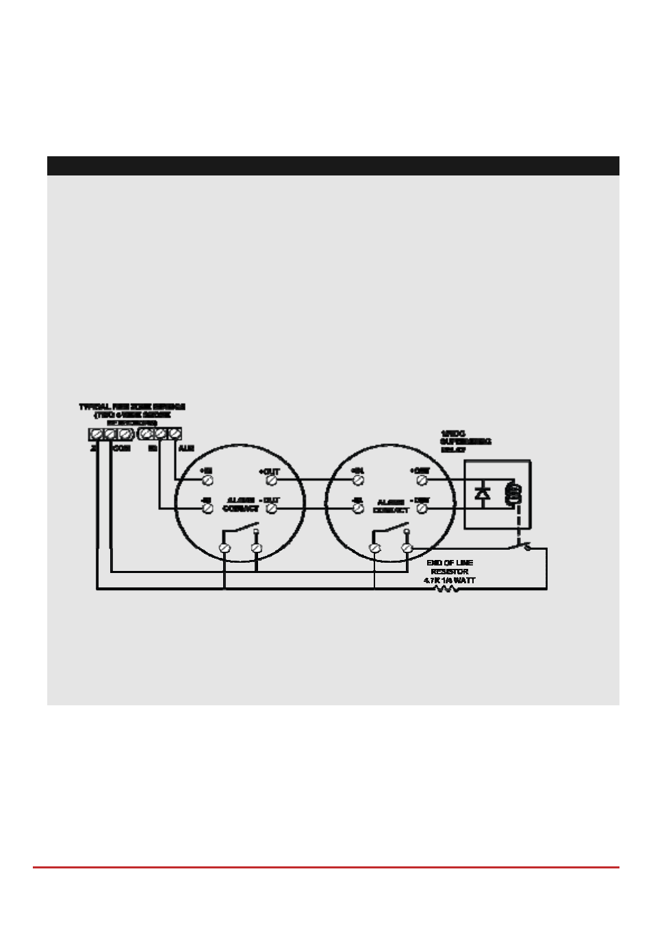
LightSYS2 supports 4‐wire smoke detectors. To connect a 4‐wire smoke detector or
device that requires resetting after an alarm condition, connect the auxiliary power
AUX and output terminals. Use a power supervision relay to supervise the 4‐wire
smoke detectors. Loss of power to the detector(s) de‐energizes the relay, causing a
break in the zone wiring and a “Fire Fault” message at the panel. Remember to define
the Output as Switched Auxiliary.
In addition, when connecting a 4‐wire smoke detector, observe the wiring guidelines
mentioned in the previous sections, along with any local requirements applicable to
smoke detectors, as per the following diagram:
To prevent a possible drop in voltage due to current requirements and distances
involved, make sure to use the appropriate wire gauge (refer to the table of gauge sizes
in) Appendix A Technical Specifications.
To increase your power supply when employing multiple auxiliary devices, you can
use the optional power supply expansion module (refer to the Wiring Power Supply
Expansion Modules section, page 46)
Wiring Internal Bell
The Bell/LS terminal provides power to the internal siren. When connecting an internal
sounding device, pay attention to the polarity.
It is important to position the BELL/LS DIP switch SW1 (see p. 37) correctly. The position
varies depending on the type of internal siren.
A maximum of 500mA may be drawn from this terminal.