RISCO Group LightSYS 2 User Manual
Page 28
Mounting and Wiring
Page 28
Notes:
1. The parallel wiring system supports parallel connections from any point along the
wiring.
2. The maximum wire run permitted is 300 meters (1000 feet) for all legs of the bus.
3. In case of bus communication problems, connect two 2.2KΩ resistors, one at each end of
the data bus terminals, between the green and yellow wires.
4. If connecting remote power supplies, do NOT connect the Red wire (+12v) between
the Power Supply Unit and LightSYS2.
5. For long cable runs, please use the correct cable as stated in Appendix A Technical
Specifications
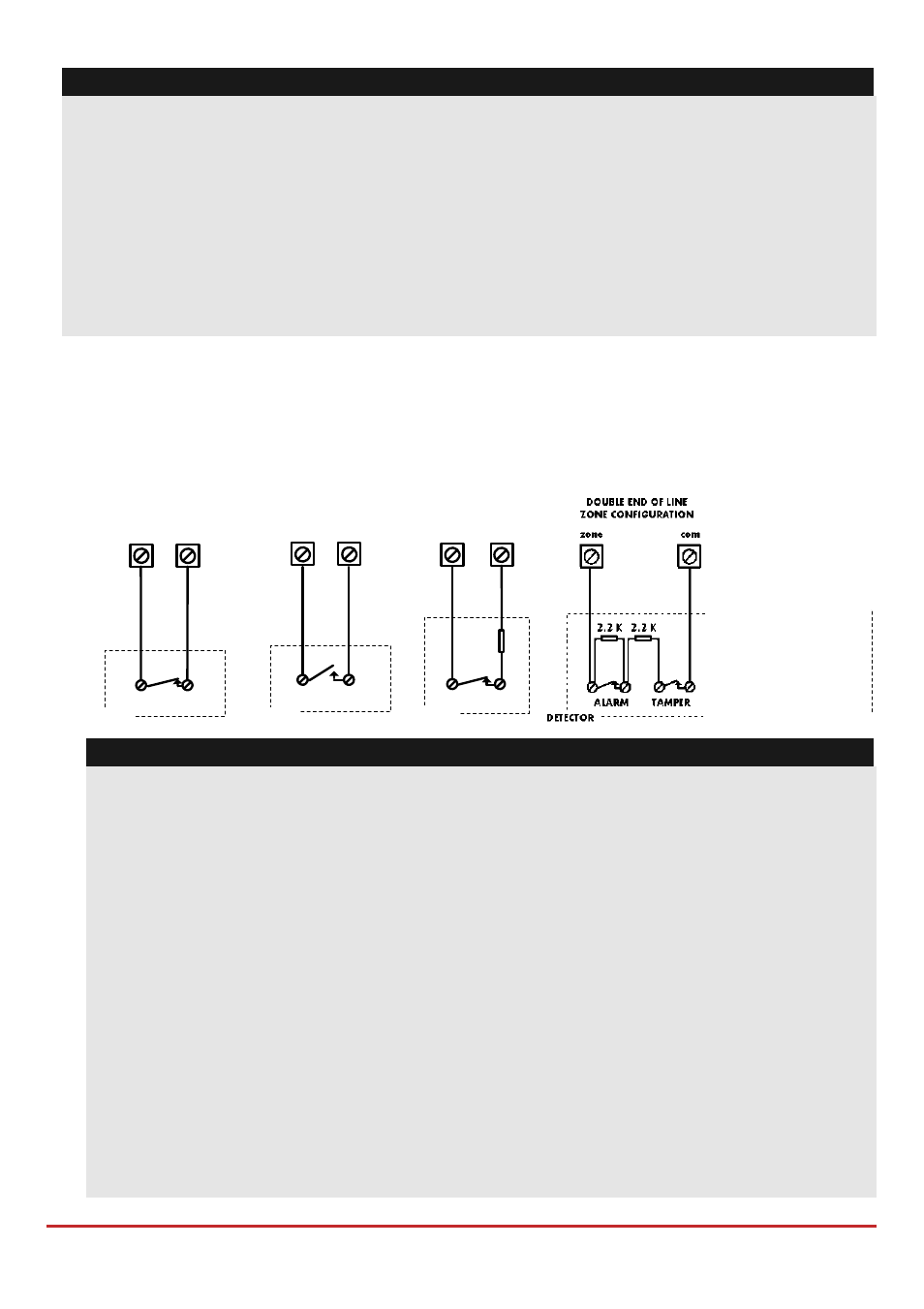
Zone Inputs Wiring
The following diagrams illustrate the various zone connections to the main unit or to
the 8 wired zones expander and possible 4‐wire smoke detector.
Notes:
1. For a zone with a tamper switch, you can use a double end‐of‐line resistor to save
additional main panel connections.
2. It is recommended that you use an end‐of‐line resistor at the far end of each
hardwired zone (16 x 2.2K resistors are supplied).
3. In the LightSYS2 you have the ability to define separately the end‐of‐line resistance
of the zones on the main unit and of the wired zones for each eight‐unit expander
block (Quick key ). Selection is done by the software with the following
available options:
ID
EOL
DEOL
ID
EOL
DEOL
0
Customized
7
4.7K
4.7k
1
2.2K
2.2K (Default)
8
3.3K
4.7K
2
4.7K
6.8K
9
1K
1K
3
6.8K
2.2K
10
3.3K
3.3K
4
10K
10K
11
5.6K
5.6K
5
3.74K
6.98K
12
2.2K
1.1K
6
2.7K
2.7K
13
2.2K
4.7K
END OF LINE ZONE
(N.O CONTACT)
zone
com
ALARM
2.2
K
DETECTOR
NORMALLY OPEN ZONE
CONFIGURATION
ALARM
zone
com
DETECTOR
NORMALLY CLOSED
ZONE CONFIGURATION
ALARM
zone
com
DETECTOR
END OF LINE ZONE
(N.C CONTACT)
2.2
K
zone
com
ALARM
DETECTOR
DOUBLE END OF LINE
ZONE CONFIGURATION
com
2.2
K
ALARM
TAMPER
zone
2.2
K
DETECTOR