RISCO Group WL Shock & Contact Detector WL T62 User Manual
Wl t62, Wireless shock & contact detector
WL T62
Wireless
Shock & Contact
Detector
Installation
Instructions
UK Tel: +44-(0)-161-655-5500
E-mail: [email protected]
ITALY Tel: +39-02-66590054
E-mail: [email protected]
SPAIN Tel: +34-91-490-2133
E-mail: [email protected]
FRANCE Tel: +33-164-73-28-50
E-mail: [email protected]
BELGIUM Tel: +32-2522-7622
E-mail: [email protected]
U.S.A Tel: +1-631-719-4400
E-mail: [email protected]
BRAZIL Tel: +55-11-3661-8767
E-mail: [email protected]
CHINA (Shanghai)
Tel: +86-21-52-39-0066
E-mail: [email protected]
CHINA (Shenzhen)
Tel: +86-755-82789285
E-mail: [email protected]
POLAND Tel: +48-22-500-28-40
E-mail: [email protected]
ISRAEL Tel: +972-3-963-7777
E-mail: [email protected]
RISCO Group Limited Warranty
RISCO Group and its subsidiaries and affiliates ("Seller") warrants its products
to be free from defects in materials and workmanship under normal use for 24
months from the date of production. Because Seller does not install or connect
the product and because the product may be used in conjunction with products
not manufactured by the Seller, Seller cannot guarantee the performance of the
security system which uses this product. Seller's obligation and liability under
this warranty is expressly limited to repairing and replacing, at Seller's option,
within a reasonable time after the date of delivery, any product not meeting the
specifications. Seller makes no other warranty, expressed or implied, and makes
no warranty of merchantability or of fitness for any particular purpose
.
In no case shall seller be liable for any consequential or incidental damages for
breach of this or any other warranty, expressed or implied, or upon any other
basis of liability whatsoever
.
Seller's obligation under this warranty shall not include any transportation
charges or costs of installation or any liability for direct, indirect, or consequential
damages or delay
.
Seller does not represent that its product may not be compromised or
circumvented; that the product will prevent any personal injury or property loss
by burglary, robbery, fire or otherwise; or that the product will in all cases provide
adequate warning or protection
.
Seller, in no event shall be liable for any direct or indirect damages or any other
losses occurred due to any type of tampering, whether intentional or
unintentional such as masking, painting or spraying on the lenses, mirrors or any
other part of the detector
.
Buyer understands that a properly installed and maintained alarm may only
reduce the risk of burglary, robbery or fire without warning, but is not insurance
or a guaranty that such event will not occur or that there will be no personal
injury or property loss as a result thereof
.
Consequently seller shall have no liability for any personal injury, property
damage or loss based on a claim that the product fails to give warning.
However, if seller is held liable, whether directly or indirectly, for any loss or
damage arising under this limited warranty or otherwise, regardless of cause or
origin, seller's maximum liability shall not exceed the purchase price of the
product, which shall be complete and exclusive remedy against seller
.
No employee or representative of Seller is authorized to change this warranty in
any way or grant any other warranty
.
WARNING: This product should be tested at least once a week
.
FCC NOTE (for 433MHz versions only):
This equipment has been tested and found to comply with the limits for a Class B digital
device, pursuant to Part 15 of the FCC rules. These limits are designed to provide
reasonable protection against harmful interference in a residential installation. This
equipment generates, uses and can radiate radio frequency energy and, if not installed
and used in accordance with the instructions, may cause harmful interference to radio
communications. However, there is no guarantee that interference will not occur in a
particular installation. If this equipment does cause harmful interference to radio or
television reception, which can be determined by turning the equipment off and on, the
user is encouraged to try to correct the interference by one or more of the following
measures:
a) Reorient or relocate the receiving antenna.
b) Increase the separation between the equipment and receiver.
c) Connect the equipment to an outlet on a circuit different from that to which the receiver
is connected.
d) Consult the dealer or an experienced radio/TV technician.
FCC Warning
The manufacturer is not responsible for any radio or TV interference caused by
unauthorized modifications to this equipment. Such modifications could void the user's
authority to operate the equipment.
FCC ID: JE4RWT71X433
RTTE Compliance Statement
Hereby, RISCO Group declares that this equipment is in compliance
with the essential requirements and other relevant provisions of Directive
1999/5/EC.
For the CE Declaration of Conformity please refer to our website:
www.riscogroup.com.
© RISCO Group 04/11
5IN1323
C
GENERAL DESCRIPTION
The WL T62 combines both a Shock detector and a
Door/Window Contact detector in a single casing for internal
use that provides reliable 24-hour perimeter protection.
The detector employs an advanced digital microprocessor to
analyze the vibration signal received from the piezo electric
sensor.
The WL T62 has a reed switch for protection against opening
doors and windows, and against any attempt to tamper the
detector using large magnets.
This detector operates in conjunction with RISCO's
programmable receivers and is powered by a standard 3-volt
lithium battery.
MAIN FEATURES
• Digital Microprocessor with Intelligent Digital Signal
Processing
• Tri-color LED enables accurate and reliable calibration, with
“over-sensitive” and “under-sensitive” indications
• Gross attack detections
• Shock and Contact detection reported to separate zones in
the receiver
• Detects attempts of magnet tampering (0.3T)
• Encapsulated bi-morph piezo electric sensor
• Dual stage adjustment potentiometer
• Back & Cover tamper protection
• Operates up to 300m (1000 ft) range (LOS)
• Uses one of more than 16 million addresses codes
• Hold on/off
• Fully supervised
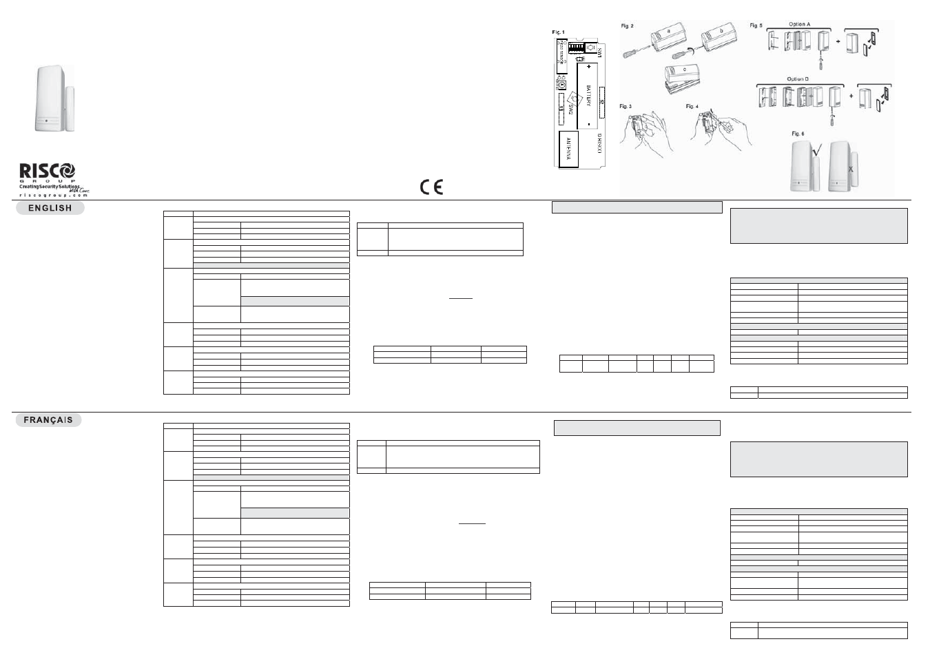
DIPSWITCHES
Dipswitch Description
1
Used to enable or disable LED
Dipswitch Position
LED
ON
(Default)
Enabled
OFF
Disabled
2
Used to determine the sensitivity of the Shock detector
Dipswitch Position
Sensitivity
ON
(Default)
High
OFF
Low
NOTE: For fine tuning use the sensitivity trimmer.
3
Used to determine the detector HOLD status (Contact Only)
Dipswitch Position
Hold Status
ON
There will be 2.5 minutes dead time between the
alarm detection transmissions. (Restore
messages will be sent immediately)
NOTE: Only one alarm message is transmitted in any
2.5 minute period.
OFF
(Default)
No dead time between alarm detection
transmissions (the unit transmits after each
detection)
4
Used to enable or disable the Contact
Dipswitch Position
Internal Reed Switch (S1)
ON
Disable
OFF
(Default)
Enable
5
Used to enable or disable the anti-sabotage function (Contact Only)
Dipswitch Position
Anti-Sabotage Reed Switch (S2)
ON
Enable
OFF
(Default)
Disable
6
Used to determine the detector RF power
Dipswitch Position
RF Power Transmission
ON
Low
OFF
(Default)
High
LED INDICATION
After each detection, the LED turns ON momentarily.
On Low Battery condition, the LED will blink during each transmission.
GREEN
Indicates an alarm condition
for Shock detection
RED
• Under-Sensitive indication of Shock detector
• Indicates an alarm condition for Contact detection
• Tamper indication
• Write message
ORANGE
Over-Sensitive indication
for Shock detection
FRONT COVER REMOVAL
Remove the front cover as described in Figure 2.
TRANSMITTER/RECEIVER COMMUNICATION SET UP
The transmitter must identify itself to the system’s receiver by writing its coded
messages into the receiver’s address memory. The receiver must identify the
Shock detector and the Contact detector separately. This is accomplished by
performing the following steps:
a. Set the receiver to the Write Mode (follow the receiver’s instructions).
b. Remove the battery from the insulation material and reinsert it into the
transmitter, paying attention to the polarity (see Fig. 3).
c. Send a separate Write message to each detector. Use Dipswitch 3, as
described in the table below, to choose a detector. To program the ID of a
Shock detector set the Dipswitch to the OFF position and send a Write message
by pressing both tamper buttons for at least 3 seconds.
Detector
Dipswitch 3
Restore
Shock detector
OFF (Default)
No
Contact Detector
ON
Yes
d. To program the ID of the Contact detector set Dipswitch 3 to ON and send a
Write message by pressing both tamper buttons for at least 3 seconds.
e. Set the receiver to the Normal mode.
f. Verify that the receiver has identified each of the detectors by generating a
tamper signal (by momentarily closing and opening both tampers). The tamper
message will be sent twice, once for each detector.
NOTE: If for any reason it is necessary to re-send a write message, press both of the
tamper buttons (back and cover) for at least 3 seconds.
INSTALLATION INSTRUCTIONS
Considerations for wireless communication
a. For best wireless communication, place the unit at the highest possible
position.
b. Temporarily attach the unit to this point using two sided adhesive tape.
c. Generate an Alarm or Tamper signal and verify that the receiver has
received the signal. If the signal is not detected, reposition the transmitter
and try again.
Considerations for shock detection
1. Select the intended position for installation, ensuring the surface is clean
and clear of any irregularities. Refer to Table 1 for details about
detection ranges for the different surface types.
2. Set the detector’s sensitivity as follows, using the sensitivity trimmer:
i. With the unit set for normal operation, use a suitable instrument to
bang or tap the protected area.
ii. If the sensitivity needs adjustment, use a screwdriver to adjust the
trimmer (turn the trimmer control clockwise to increase sensitivity
or counter-clockwise to reduce sensitivity).
iii. Repeat steps i and ii until the desired sensitivity level is achieved.
If required, you can set Dipswitch 2 to OFF to reduce sensitivity
range.
3. Close the front cover.
Table 1: Typical Detection Range
Surface
Concrete
Brick Wall
Steel
Glass Wood Plywood
Radius
1.5m
5ft
2.5m
8.2ft
3m
10ft
3.5m
11.5ft
3.5m
11.5ft
4m
13ft
The above values are typical and are subject to practical testing, which must be
performed for each installation. In some environments, these values may differ
from the values listed above.
Considerations for magnet installation
a. Install the WL T62 in a place that enables you to install the magnet in
parallel to it (for example: door frame).
b. Install the magnet on the right side of the WL T62 as indicated in Figure 6.
NOTES:
• Maximum distance of the magnet from the detector is 20mm (0.7inch).
• Position the magnet as close as possible to the same plane level as the back surface of
the WL T62.
• The mark on the magnet's plastic case should be opposite to the mark on the detector's
case.
• Placing the magnet on the wrong side of the WL T62 will cause a tamper alarm signal
.
FINAL MOUNTING
Separate the back part of the transmitter (Fig. 4), and mount all the parts in
place (Fig. 5).
SPECIFICATIONS
ELECTRICAL
Battery Type:
CR123 3V Lithium Battery
Current Consumption:
10µA standby
Frequency:
433.92 / 868.65 MHz
Supervision Transmission:
868.65 MHz model: every 15 minutes
433.92 MHz model: every 65 minutes
Modulation Type:
ASK
Battery Life:
3 years depends on usage
PHYSICAL
Size:
81 x 35 x 32 mm (3.2 x 1.37 x 1.27 in.)
ENVIRONMENTAL
RF immunity:
According to EN-50130-4
Operating temperature:
0°C to 55°C (32°F to 131°F)
Storage temperature:
-20°C to 60°C (-4°F to 140°F)
Maximum humidity:
95% non-condensing
Specifications are subject to change without prior notice.
Should any questions arise please contact your supplier.
ORDERING INFORMATION
Model Description
WL T62
WL Shock & Contact, 433/868 MHz, White/Brown
DESCRIPTION GENERALE
Le WL T62 combine un détecteur de choc et un détecteur
d'ouverture sans fil dans un même boîtier destiné à une
utilisation intérieur, et qui offre une protection fiable 24h/24 du
p
érimètre couvert. Grâce à son microprocesseur numérique
de pointe, le d
étecteur analyse tout signal de vibration qui lui
est envoy
é par le capteur piézo-électrique.
Le WL T62 intègre un contact reed pour une protection contre
l'ouverture des portes et des fenêtres, et contre le sabotage
du détecteur en utilisant un aimant puissant.
Aliment
é par une pile au lithium de 3V standard, il fonctionne
en combinaison avec les r
écepteurs programmables de
RISCO.
CARACTERISTIQUES PRINCIPALES
• Microprocesseur avec traitement intelligent du signal
num
érique
• Diode
électroluminescente tricolore (LED) pour un calibrage
pr
écis et fiable, avec indications "d'excès" et "d'insuffisance"
de sensibilit
é
• D
étection d'attaques brutales
• Détection de choc et d'ouverture gérées sur 2 zones
différentes du récepteur
• Détecte les tentatives de sabotage par aimant (0.3T)
• Capteur pi
ézo-électrique bimorphe intégré
• Potentiom
ètre à double réglage
• Autoprotection à l'arrachement et à l'ouverture
• Portée allant jusqu'
à 300 m. (1000 ft.) (Champ libre)
• Utilise un code d'adresse parmis plus de 16 millions
• Information type maintenue (On/Off)
• Dur
ée de vie étendue de la pile
• Enti
èrement supervisé
DIPSWITCHES
Dipswitch Description
1
Utilisé pour activer ou désactiver la LED
Position du DIP
LED
ON
(par défaut))
Activé
OFF
Désactivé
2
Utilisé pour déterminer la sensibilité du détecteur de choc
Position du DIP
Sensibilité
ON
(par défaut)
Elevée
OFF
Faible
NOTE : Pour un réglage fin, utiliser le potentiomètre de sensibilité.
3
Sert à déterminer l'état de MAINTIEN du détecteur (Contact seulement)
Position du DIP
Etat de Maintien
ON
Un temps mort de 2 min. 30 s'écoulera entre les
detections d'alarme transmises (Les
messages de
rétablissement seront envoyés immédiatement)
REMARQUE : Un seul message d'alarme est émis par
intervalle de 2 min. 30.
OFF
(par défaut)
Pas de temps mort entre les détections d'alarme
transmises (l'appareil émet après chaque
détection)
4
Utilisé pour activer ou désactiver le contact magnetique
Position du DIP
Contact reed Interne (S1)
ON
Désactivé
OFF
(par défaut)
Activé
5
Utilisé pour activer ou non la fonction anti-sabotage (Contact seulement)
Position du DIP
Contact reed Anti-Sabotage (S2)
ON
Activé
OFF
(par défaut)
Désactivé
6
Sert à déterminer la puissance de transmission RF.
Position du DIP
Transmission RF
ON
Faible
OFF
(par défaut)
Elevée
INDICATIONS LED
Apr
ès chaque détection, la diode LED s'allume momentanément.
Lorsque la pile est faible (batterie faible) – la diode LED clignote
à chaque
transmission.
VERTE
Indique une condition d'alarme pour la détection de choc
ROUGE
• Indique une insuffisance de sensibilit
é pour la détection de choc
• Indique une condition d'alarme pour la détection d'ouverture
• Indication de sabotage
• Message d'écriture
ORANGE
Indique un exc
ès de sensibilité
pour la détection de choc
RETRAIT DU COUVERCLE FRONTAL
Enlever le couvercle comme décrit en figure 2.
PARAMETRAGE DE LA COMMUNICATION TRANSMETTEUR/
RÉCEPTEUR
Le transmetteur doit s'identifier aupr
ès du récepteur du système en inscrivant ses
messages cod
és dans le registre d'adresses du récepteur. Ce dernier voit le
détecteur de choc et le détecteur d'ouverture s
éparément. Cette opération
s'accomplit en ex
écutant les étapes suivantes :
a. R
églez le récepteur en mode écriture (suivez pour cela les instructions
correspondantes).
b. Retirez la pile de sa protection isolante et r
éinsérez-la dans le transmetteur en
respectant la polarit
é indiquée (cf. fig. 3).
c. Envoyez un message d'écriture de chaque détecteur s
éparément. A l'aide du
Dipswitch 3, s
électionnez un détecteur selon les instructions du tableau ci-
dessous. Pour programmer l'ID du détecteur de choc, r
églez le Dipswitch en
position OFF et envoyez un message d'écriture en appuyant sur les deux
contacts d'autoprotection pendant au moins 3 secondes.
Détecteur
Dipswitch 3
Restauration
Détecteur de choc
Arrêt (OFF) (par défaut)
Non
Détecteur d'ouverture
Marche (ON)
Oui
d. Pour programmer l'ID du détecteur d'ouverture, réglez le Dipswitch 3 en position
ON et envoyez un message d'écriture en appuyant sur les deux contacts
d'autoprotection pendant au moins 3 secondes.
e. R
églez le récepteur en mode normal.
f. V
érifiez que chaque détecteur a bien été identifié par le récepteur : pour cela,
g
énérez un signal d'autoprotection (en fermant et ouvrant momentanément les
deux AP). Le message d'AP sera envoyé 2 fois, pour les 2 détecteurs.
REMARQUE : si pour une raison quelconque, il s'avère nécessaire de renvoyer un
message d’
écriture, il suffit pour cela d'appuyer simultanément sur les deux contacts
d'autoprotection (arri
ère et couvercle) pendant au moins 3 secondes.
INSTRUCTIONS D'INSTALLATION
Considérations pour la communication sans fil
a. Pour une meilleure communication, placez l'appareil le plus haut
possible.
b. Fixez provisoirement l'appareil en ce point en utilisant de l'adh
ésif double
face.
c. Générer un signal d'alarme ou d'AP et v
érifiez que le récepteur a bien
re
çu le signal. Si le signal d'alarme n'a pas été détecté, repositionnez le
transmetteur et r
éessayez.
Considérations pour la détection de choc
1. Choisissez l'endroit souhaité pour l'installation, en vous assurant que la
surface est bien propre et nette de toutes asp
érités. Se reporter au
tableau 1 pour consulter les port
ées de détection selon les différents
types de surfaces.
2. Ajuster la sensibilit
é du détecteur comme suit, en vous servant du
potentiomètre de sensibilit
é :
(i) L'appareil
étant en mode de fonctionnement normal, feignez, à l'aide
d'un instrument adapt
é, une intrusion (en cognant ou frappant) au
sein de la zone prot
égée.
(ii) Si la sensibilit
é requiert un ajustement, ajustez le réglage à l'aide d'un
tournevis (dans le sens des aiguilles d'une montre pour augmenter la
sensibilit
é, et dans le sens inverse pour la réduire).
(iii) Renouvelez les
étapes (i) et (ii) jusqu'
à obtenir le niveau de
sensibilit
é souhaité. Si nécessaire, vous pouvez mettre le Dipswitch
2 sur OFF pour réduire la sensibilité.
3. Fermez le couvercle frontal.
Tableau 1 : Port
ées typiques de détection
Surface
Béton
Mur de briques
Acier
Verre
Bois
Contreplaqué
Rayon
1,5 m
2,5 m
3m
3,5 m
3,5 m
4m
Les valeurs indiqu
ées ci-dessus sont des valeurs typiques et doivent être
soumises
à un test pratique à réaliser à chaque installation. Dans certains
environnements, ces valeurs peuvent
être différentes de celles du tableau ci-
dessus.
Considérations pour l'installation d'un contact magnétique
a. Installer le WL T62 à un endroit qui vous permet d'installer l'aimant en
parallèle à ce dernier (par exemple : cadre de porte).
b. Installer l'aimant sur le côté droit du WL T62 comme indiqué en Figure 6.
NOTES :
• La distanceMaximum entre l'aimant et le détecteur est de 20mm.
• Positionner l'aimant pour que sa surface de pose soit la plus proche possible de la
surface de pose du WL T62.
•
La marque faite sur le boîtier en plastique de l'aimant doit se trouver à l'opposé de la
marque faite sur le boîtier du détecteur
.
• Posistionner l'aimant du mauvais côté du WL T62 provoquera un signal d'AP.
ASSEMBLAGE FINAL
S
éparez la partie arrière de l’émetteur (Fig. 4), et montez toutes les pièces
(Fig. 5).
SPECIFICATIONS
ELECTRIQUES
Type de batterie :
pile lithium 3V CR123
Consommation
électrique :
10µA en veille
Fr
équence :
433.92 / 868.65 MHz
Transmission de supervision :
Modèle 868.65 MHz : toutes les15 minutes
Modèle 433.92 MHz : toutes les 65 minutes
Type de modulation :
ASK
Dur
ée de vie de la pile :
3 ans selon utilisation
PHYSIQUES
Dimensions :
81 x 35 x 32 mm (3.2 x 1.37 x 1.27 in.)
ENVIRONNEMENTALES
Immunit
é RF :
selon la norme EN-50130-4
Temp
érature de
fonctionnement :
de 0°C
à 55°C (32°F à 131°F)
Temp
érature de stockage :
de -20°C
à 60°C (-4°F à 140°F)
Humidit
é maximum :
95% sans condensation
Ces sp
écifications sont susceptibles d'être modifiées sans avis préalable.
Si vous avez des questions, veuillez contacter votre fournisseur.
INFORMATION DE COMMANDE
Modèle Description
WL T62
Détecteur de choc et d'ouverture sans fil, 433/868 MHz,
Blanc/Marron