Power on the l30 raid chassis, Setting up the l30 raid chassis, Primary expansion 1 expansion 2 – Grass Valley K2 Storage System Instruction Manual v.3.2 Sep.24 2007 User Manual
Page 511: Dp0 dp1, Sas cables
September 7, 2007
K2 Storage System Instruction Manual
511
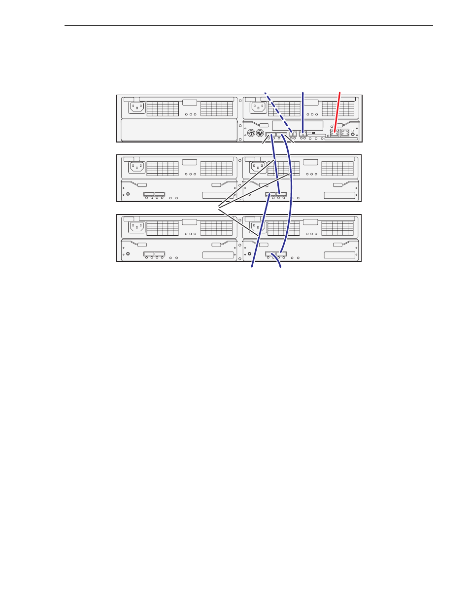
Setting up the L30 RAID chassis
If you have more Expansion chassis than those illustrated, continue the indicated
cabling pattern, alternating connections for additional Expansion chassis between
DP1 and DP0. Expansion chassis 1, 3, 5, 7, and 9 connect to DP1. Expansion chassis
2, 4, 6, 8, and 10 connect to DP0.
Once the RAID storage is connected and configured, do not swap Expansion chassis
or otherwise reconfigure storage. If you connect an Expansion chassis in a different
order or to the wrong controller, the controller will see a configuration mismatch and
fault.
Power on the L30 RAID chassis
Connect power cords and power up RAID storage devices as follows:
1. Verify power and cabling.
2. Press and hold down the power button on the controller, as shown.
FLT/LNK
FLT
RDY
DP-OUT
PS
FLT CLR
DP-IN
FLT/LNK
FLT
RDY
DP-OUT
PS
FLT CLR
DP-IN
FLT/LNK
FLT
RDY
DP-OUT
PS
FLT CLR
DP-IN
FLT/LNK
FLT
RDY
DP-OUT
PS
FLT CLR
DP-IN
BBU IN
MODEM
FLT/LNK
HPE
FLT
A/L
BACKUP
ACT/LNK
LNK/ACT
FLT
HP
5 4 3 2
RDY
LAN
BAT
MNT
ACS
MC
DP1
DP0
HP
1 0
BBU IN
MODEM
FLT/LNK
HPE
FLT
A/L
BACKUP
ACT/LNK
LNK/ACT
FLT
HP
5 4 3 2
RDY
LAN
BAT
MNT
ACS
MC
DP1
DP0
HP
1 0
Primary
Expansion 1
Expansion 2
DP0
DP1
To
Exp
a
n
s
ion
3
To
Exp
a
n
s
ion
4
To control port
on GigE
s
witch
To K2 Medi
a
S
erver A
To NH
s
erver
(option
a
l)
S
A
S
c
ab
le connector
s
a
re keyed to DP IN/OUT port
s
.
SAS cables