Setting up the level 20r redundant gige switches – Grass Valley K2 Storage System Instruction Manual v.3.2 Sep.24 2007 User Manual
Page 437
September 7, 2007
K2 Storage System Instruction Manual
437
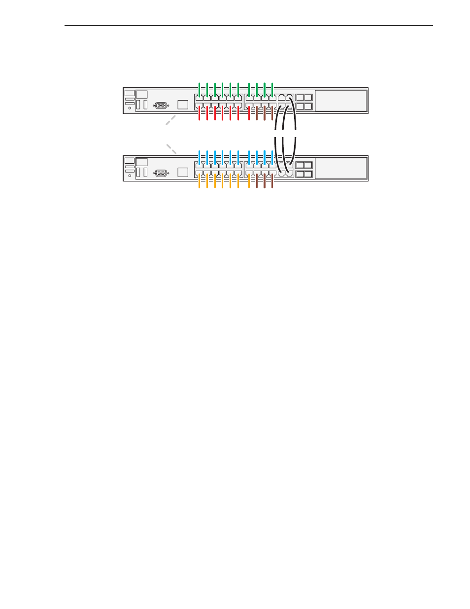
Setting up the Level 20R redundant GigE switches
2900 series switch
To the media ports on switch A, make the “A” media (iSCSI) network connection
from each K2 Media Client. Also make two media (iSCSI) connections from K2
Media Server A.
To the media ports on switch B, make the “B” media (iSCSI) network connection
from each K2 Media Client. Also make two media (iSCSI) connections from K2
Media Server B.
To the control ports on switch A, make one connection from each K2 Media Client,
from RAID controller 0, and from the control point PC. Also make the control
network connection and the FTP network connection from K2 Media Server A.
To the control ports on switch B, make the second control connection from each
K2 Media Client, and from RAID controller 1. Also make the control network
connection and the FTP network connection from K2 Media Server B.
If you have other iSCSI clients, such as Aurora Edits, that have just one iSCSI
connection and one control connection, approximately half of the clients should be
connected to switch A and half of the clients should be connected to switch B. In a
failover event, only the clients connected to one of the switches will remain
operational, so make connections accordingly. Connect the client’s iSCSI
connection to one of the media ports on a switch and the client’s control connection
to one of the control ports on the same switch.
Interconnect switch A and switch B with three 1 Gig ISLs.
If you have optional NH1 K2 Media Servers, for each server connect its FTP
network connection and its control network connection to the control ports on the
same switch. Balance servers between switch A and switch B.
If you have optional NH1-10GE K2 Media Servers, for each server connect its 10
Gig FTP network connection to a 10 Gig port on the rear of the switch and connect
its control network connection to a control port on the same switch. Balance servers
between switch A and switch B. Switches have two 10 Gig connectors standard and
two 10 Gig connectors optional, so to connect three or four severs to a switch, you
must first install the optional 10 Gig connectors in the switch.
“Level 20R system description” on page 434
for a diagram of the complete
system.
Refer to cabling procedures later in this chapter for the GigE connections at each of
the devices of the K2 Storage System.
Control port
s
Medi
a
(i
S
C
S
I) port
s
Control port
s
Medi
a
(i
S
C
S
I) port
s
B
A
Inter-
S
witch Link
s
(I
S
L
s
)
10 Gig connection
s
to
re
a
r of
s
witch for option
a
l
NH1-10GE
s
erver
s