Amplifier backup – ATEIS IDA8 User Manual
Page 81
Product Features
81
© 2012 ATEÏS
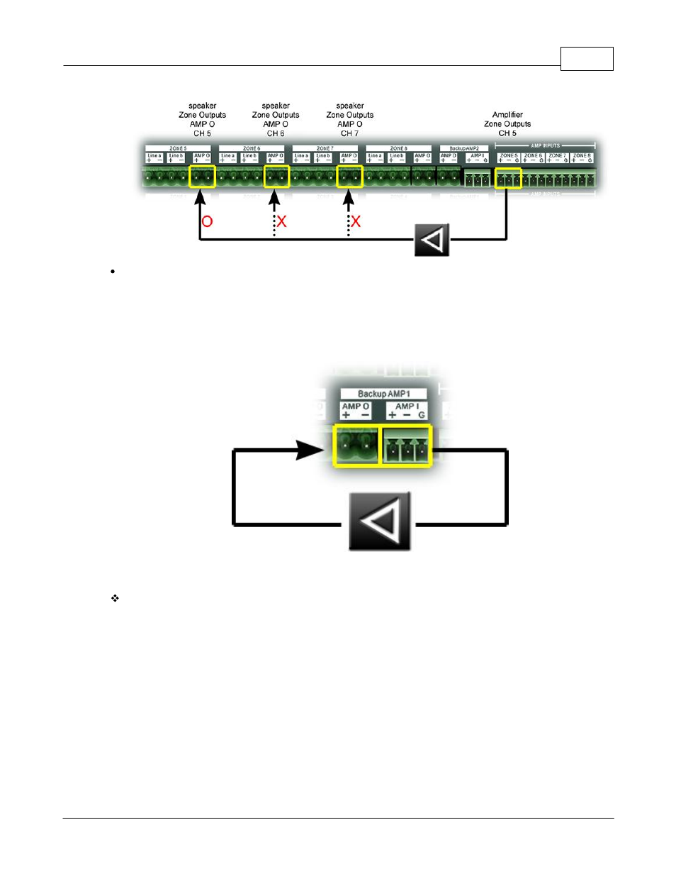
Backup Amplifier Connections:
The is for the connection of amplifiers for backup. In above figure(Basic Amplifier Connection), B1,
B2 are backup amplifiers. There two connectors for each backup amplifier. Trace the wiring. The
audio signal starts from the AMP I connector, goes into the amplifier's input, then is gained by the
amplifier and input to the AMP O connector. The following figure is an example of a backup amplifier
connection.
4.1.6.2
Amplifier Backup
Basic Concept:
The IDA8 system applies a flexible mechanism for amplifier backup. Before digging deeper into the
rules of the amplifier backup, let's first understand its basic concept. In most of cases, audio goes
through the normal amplifier. Once the normal amplifier fails, the IDA8 will switch to the backup
amplifier to ensure that the system is still functioning. Meanwhile, the technician should analyze the
problem, which in this case is, to replace the non-working amplifier with the functioning amplifier.
The figure below(Audio Routing without Backup Amplifier) shows the case of audio routing using a
normal amplifier. The number in the figure below is the sequence of audio path.