Rear panel – ATEIS IDA8 User Manual
Page 72
ATEIS - IDA8
72
© 2012 ATEÏS
4.1.4.3
Rear Panel
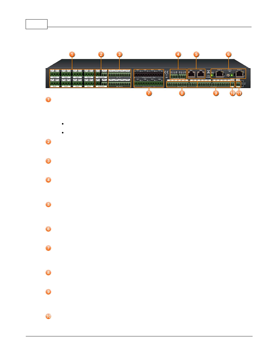
Speaker Zone Outputs:
There are 8 zones for speaker & amplifier connection. each zone consists of following connectors
(from left to right):
connector of line speaker
connector of 100V audio coming from amplifier.
Backup Amplifier I/Os:
Two backup amplifier connectors included 0 dB to amplifiers and 100V return from amplifiers.
Amplifier Zone Outputs:
8 Zone 0dB output to amplifiers.
Bypass Mode Outputs:
This port is used to share the bypass mode microphone signals through the IDA8C-IDA8S network
(only needed when using fiber optic network).
PDC(Peripherals Device Controller) Connectors:
Two RJ-45 connectors are used to connect the consoles or peripheral devices. For examples, PSS
AS, URC AS, PPM AS, ... are connect to IDA8S via this connector.
Local Ateis Net Connectors:
The optional card for building a local dedicated IDA8C-IDA8S network.
Configurable Audio I/Os:
Two configurable 0dB audio I/O port A and B. Each port is available to assemble an audio card.
There are 4 channels on each audio I/O card.
Contact Outputs:
8 logic output channels
to close/open circuits for an external device, this contact is normally open.
Evacuation Inputs:
9 evacuation contact inputs allow the monitoring of external contact. They also can be used in UGA
mode and triggered by a voltage polarization change.
24V DC Output:
This connector supplies a 24VDC source.