Logic control – ATEIS IDA8 User Manual
Page 506
ATEIS - IDA8
506
© 2012 ATEÏS
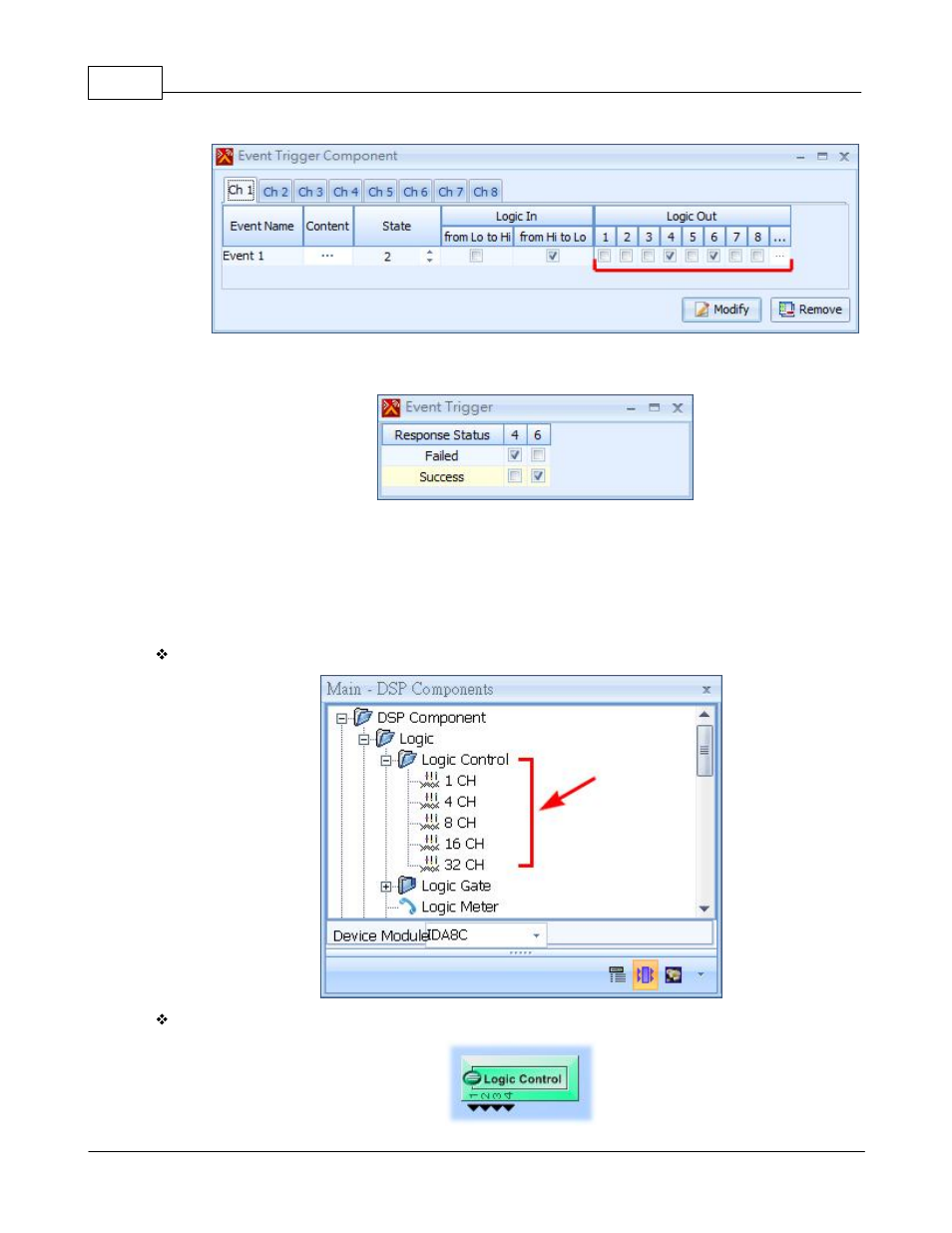
In the above figure, the logic output channel 4 and 6 are selected. For more settings, click the
grid cell [...]:
In the above figure, the settings means when the Event 1 is Failed, output 4 will be 1 and output
6 will be 0, and when Event1 is successfully executed the output 4 will be 0 and the output 6 will
be 1.
6.12.5 Logic Control
Component Template:
Component Appearance: