Zilog Z16C35 User Manual
Page 97

ISCC
User Manual
UM011002-0808
91
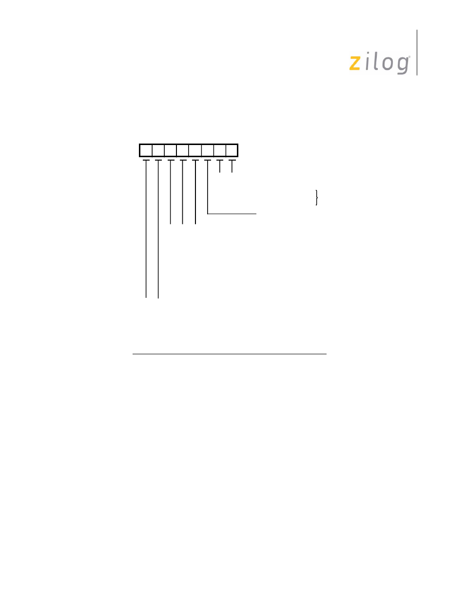
Figure 5-2 shows the bit configuration for the multiplexed mode and includes (in Channel
B only) the address decoding select described later.
Figure 5–31. WR0 in the Multiplexed Bus Mode
The following bit description for WR0 is identical for both versions except where speci-
fied.
Bits D7 and D6 are the CRC Reset Codes 1 and 0.
Bit combination 00 is a Null Command
This command has no effect on the ISCC SCC cell and is used when a write to WR0 is
necessary for some reason other than a CRC Reset command.
Bit combination 01 is the Reset Receive CRC Checker Command
This command is used to initialize the receive CRC circuitry. It is necessary in synchro-
nous modes (except SDLC) if the Enter Hunt Mode command in Write Register 3 is not
issued between received messages. Any action that disables the receiver initializes the
CRC circuitry. Resetting the Receive CRC Checker command is accomplished automati-
cally in SDLC mode.
Null Code
Null Code
Select Shift Left Mode
Select Shift Right Mode
Null Code
Null Code
Reset Ext/Status Interrupts
Send Abort
Enable Int on Next Rx Character
Reset Tx Int Pending
Error Reset
Reset Highest IUS
Null Code
Reset Rx CRC Checker
Reset Tx CRC Generator
Reset Tx Underrun/EOM Latch
Write Register 0 (multiplexed bus mode)
D6
D7
D5 D4 D3 D2 D1 D0
0
0
1
1
0
0
1
1
0
1
0
1
0
1
0
1
0
0
1
1
0
1
0
1
0
0
1
1
0
1
0
1
0
*
0
0
0
0
1
1
1
1
* B Channel Only
Page 91 of 316
