Zilog Z16C35 User Manual
Page 81
ISCC
User Manual
UM011002-0808
75
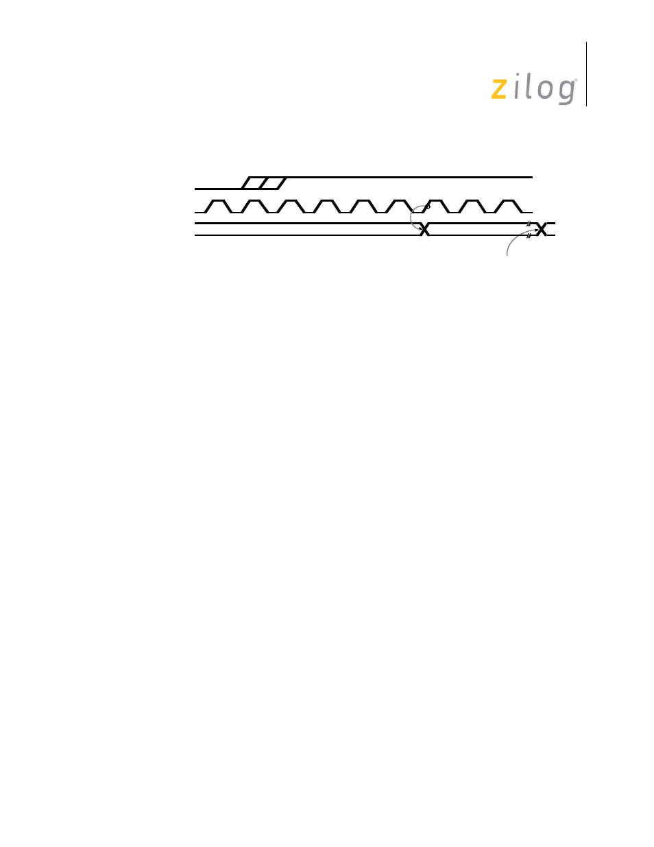
Figure 4–27. /SYNC as an Output
If the Address Search Mode bit (D2) in WR3 is set to “0” the address recognition logic is
disabled and all received frames are transferred to the receive data FIFO. In this mode the
software must perform any address recognition.
If the Address Search Mode bit is set to “1”, only those frames whose address matches the
address programmed in WR6 or the global address (all “1s”) will be transferred to the
receive data FIFO.
The address comparison will be across all eight bits of WR6 if the Sync Character Load
inhibit bit (D1) in WR3 is set to “0”. The comparison may be modified so that only the
four most significant bits of WR6 must match the received address. This mode is selected
by setting the Sync Character Load inhibit bit to “1”. In this mode, however, the address
field is still eight bits wide. The address field is transferred to the receive data FIFO in the
same manner as data. It is not treated differently than data.
The number of bits per character is controlled by bits D7 and D6 of WR3. Five, six, seven,
or eight bits per character may be selected via these two bits. The data is right-justified in
the receive buffer. The ISCC merely takes a snapshot of the receive data stream at the
appropriate times, so the “unused” receive buffer are only the bits following the character.
An additional bit carrying parity information may be selected by setting bit D6 of WR4 to
“1”. This also enables parity in the transmitter. The parity sense is selected by bit D1 of
WR4. Parity is not normally used in SDLC mode. The character length may be changed at
any time before the new number of bits have been assembled by the receiver. Care should
be exercised, however, as unexpected results may occur. A representative example,
switching from five bits to eight bits and back to five bits is shown in Figure 4-13.
State changes in one
/RTxC clock cycle
/RTxC
PCLK
/SYNC
Page 75 of 316