1 asynchronous transmit, Asynchronous transmit – Zilog Z16C35 User Manual
Page 56
ISCC
User Manual
UM011002-0808
50
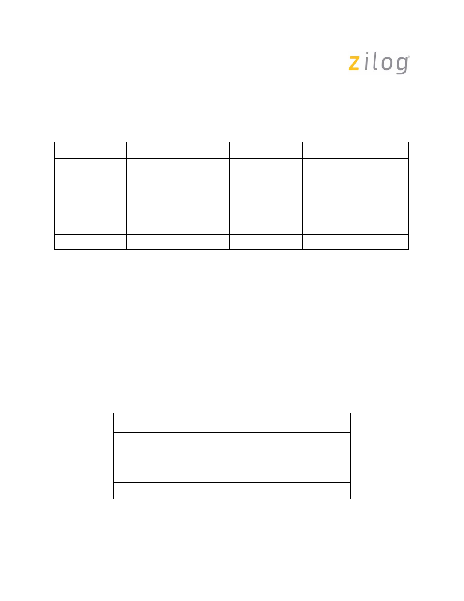
WR7 and all of WR10 except D6 and D5. Bits that are ignored may be programmed with
“1” or “0” or not at all. See Table 4-1 below
4.2.1 Asynchronous Transmit
Characters are loaded from the transmit buffer to the shift register where they are given a
start bit and a parity bit (if programmed), and are shifted out to the TxD pin. Each time the
transmit buffer becomes empty the Tx Empty bit in RR0 is set to 1 and, optionally, an
interrupt or DMA request can be generated.
The number of bits transmitted per character is controlled both by Bits D6 and D5 in
WR5, and the way the data is formatted within the transmit buffer. The bits in WR5 allow
the option of five, six, seven, or eight bits per character. When five bits per character is
selected the data may be formatted before being written to the transmit buffer to allow
transmission of from one to five bits per character.
This formatting is shown in Table 4-2.
Table 4–9. Write Register Bits Ignored in Asynchronous Mode
Register
D7
D6
D5
D4
D3
D2
D1
D0
WR3
x
x
x
WR4
x
x
WR5
x
x
WR6
x
x
x
x
x
x
x
x
WR7
x
x
x
x
x
x
x
x
WR10
x
x
x
x
x
x
Table 4–10. Transmit Bits per Character
Bit 7
Bit 6
0
0
5 or less bits/character
0
1
7 bits/character
1
0
6 bits/character
1
1
8 bits/character
Page 50 of 316