Zilog Z16C35 User Manual
Page 47
ISCC
User Manual
UM011002-0808
41
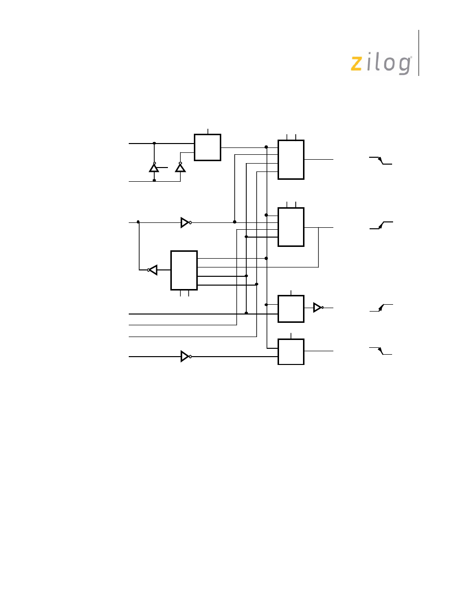
Figure 3–12. Clock Multiplexer
Selection of the clocking options may be done anywhere in the initialization sequence, but
the final values must be selected before the receiver, transmitter, baud rate generator, or
DPLL are enabled to prevent problems from arbitrarily narrow clock signals out of the
multiplexers. The same is true of the crystal oscillator, in that the output should be allowed
to stabilize before it is used as a clock source.
Also shown are the edges used by the receiver, transmitter, baud rate generator and DPLL
to sample or send data or otherwise change state. For example, the receiver samples data
on the falling edge, but since there is an inversion in the clock path between the /RTxC pin
and the receiver, a rising edge of the /RTxC pin samples the data for the receiver.
OSC
/SYNC
/RTxC
OSC
Receiver
RX
TX
DPLL
BRG
/TRxC
Baud Rate
Generator Out
Tx DPLL Out
Rx DPLL Out
PCLK
Echo
Baud Rate
Generator
DPPL
Transmitter
Echo
Page 41 of 316
- S3F94C8 (11 pages)
- S3F80QB (29 pages)
- S3F8S19 (38 pages)
- Z51F6412 (96 pages)
- Z51F6412 (54 pages)
- Z51F6412 (55 pages)
- EZ80F93 (11 pages)
- Z16F6411 (20 pages)
- Z16F6411 (216 pages)
- EZ80F93 (13 pages)
- ZMOT0BSB (314 pages)
- ZMOT0BSB (582 pages)
- Z8F083A (14 pages)
- Z8F2480 (17 pages)
- Z8F082A (18 pages)
- Z8F082A (15 pages)
- Z8F6423 (83 pages)
- Z8F0822 (17 pages)
- Z8F2480 (19 pages)
- Z8F2480 (18 pages)
- Z8F6423 (18 pages)
- Z8F6423 (27 pages)
- Z8F6482 (50 pages)
- EZ80F915 (411 pages)
- EZ80F91NAA (34 pages)
- EZ80F91 (41 pages)
- EZ80L92 (40 pages)
- EZ80L92 (26 pages)
- EZ80L92 (79 pages)
- EZ80F91GA (469 pages)
- EZ80L92 (10 pages)
- eZ80F92 (87 pages)
- Z16FMC6 (520 pages)
- Z8FMC16 (26 pages)
- Z16FMC6 (41 pages)
- ZUSBOPTS (38 pages)
- ZUSBOPTS (59 pages)
- Z16FMC6 (26 pages)
- Z16FMC6 (8 pages)
- ZMOT1AHH (25 pages)
- ZMOT0BSB (34 pages)
- EZ80F915 (78 pages)
- EZ80190 (87 pages)
- EZ80L92 (86 pages)
- EZ80F91GA (127 pages)