4 bit-oriented synchronous mode, Bit-oriented synchronous mode – Zilog Z16C35 User Manual
Page 75
ISCC
User Manual
UM011002-0808
69
enabled by setting bit D0 of WR3 to “1”. If the receiver is already enabled it may be
placed in Hunt mode by setting bit D4 of WR3 to “1”. Once the receiver leaves Hunt mode
the transmitter is activated on the following character boundary.
4.4 BIT-ORIENTED SYNCHRONOUS MODE
Synchronous Data Link Control mode (SDLC) uses synchronization characters similar to
Bisync and Monosync modes (such as flags and pad characters), but it is a bit-oriented
protocol instead of byte-oriented protocol. High-Level synchronous Data Link Communi-
cation (HDLC) pro-tocol is identical to SDLC except for differences in framing and can be
handled by the ISCC using the SDLC mode. The discussions on SDLC which follow are
equally applicable to HDLC.
Any data communication link involves at least two stations. The station that is responsible
for the data link and issues the commands to control the link is called the “primary sta-
tion”. The other station is a “secondary station”. Not all information transfers need to be
initiated by a primary station. In SDLC mode, a secondary station can be the initiator.
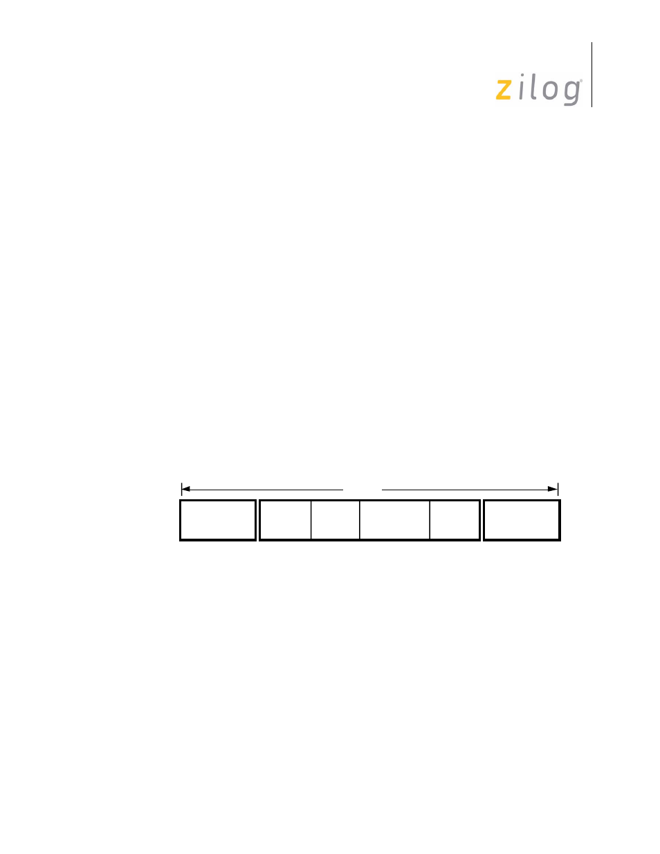
The basic format for SDLC is a “frame” (Figure 4-11). The information field is not
restricted in format or content and can be of any reasonable length (including zero). Its
maximum length is that which can be expected to arrive at the receiver error-free most of
the time. Hence, the determination of maximum length is a function of communication
channel error rate.
Figure 4–26. SDLC Message Format
Two flags that delineate the SDLC frame serve as reference points when positioning the
address and control fields, and they initiate the transmission error check. The ending flag
indicates to the receiving station that the 16-bits just received constitute the frame check.
The ending flag could be followed by another frame, another flag, or an idle. This means
that when two frames follow one another, the intervening flag may simultaneously be the
ending flag of the first frame and the beginning flag of the next frame. Since the SDLC
mode does not use characters of defined length, but rather works on a bit-by-bit basis, the
01111110 (7EH) flag can be recognized at any time.
To ensure that the flag is not sent accidentally, SDLC procedures require a binary “0” to
be inserted by the transmitter after the transmission of any five contiguous “1s”. The
Beginning Flag
01111110
8 Bits
Frame
Check
16 Bits
Information
Any Number
Of Bits
Address
8 Bits
Control
8 Bits
Ending Flag
01111110
8 Bits
Frame
Page 69 of 316