Zilog Z16C35 User Manual
Page 35
ISCC
User Manual
UM011002-0808
29
When the time-constant is to be changed, the generator should be stopped first by writing
to an enable bit in WR14. After loading the time constant, the BRG can be started again.
This ensures the loading of a correct time constant, but loading will not be taking place
until zero count or a re-set occurs.
If neither the transmit clock nor the receive clock are programmed to come from the
/TRxC pin, the output of the baud rate generator may be made available for external use
on the /TRxC pin.
The clock source for the baud rate generator is selected by bit D1 of WR14. When this bit
is set to “0,” the baud rate generator uses the signal on the /RTxC pin as its clock, indepen-
dent of whether the /RTxC pin is a simple input or part of the crystal oscillator circuit.
When this bit is set to “1,” the baud rate generator is clocked by PCLK. To avoid metasta-
ble problems in the counter, this bit should be changed only while the baud rate generator
is disabled, since arbitrarily narrow pulses can be generated at the output of the multi-
plexer when it changes state.
The BRG is enabled while bit DO of WR14 is set to 1 and disabled while this bit is set to 0
and it is disabled after a hardware reset. To prevent metastable problems when the baud
rate generator is first enabled, the enable bit is synchronized to the baud rate generator
clock. This introduces an additional delay when the baud rate generator is first enabled.
This is shown in Figure 3-2. The baud rate generator is disabled immediately when bit D0
of WR14 is set to “0,” because the delay is only necessary on start-up. The baud rate gen-
erator may be enabled and disabled on the fly, but this delay on start-up must be taken into
consideration.
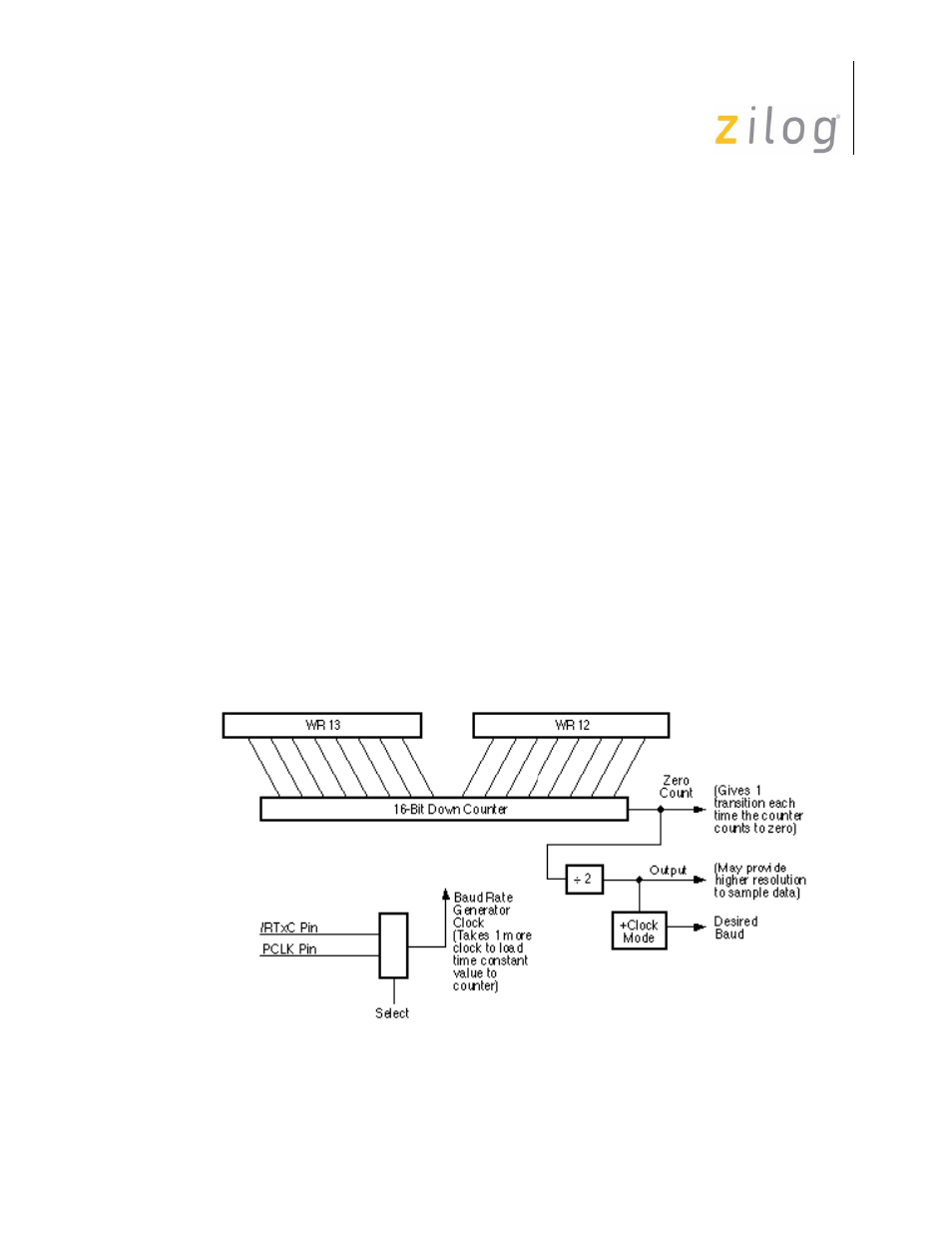
Figure 3–4. Baud Rate Generator
Page 29 of 316