Zilog Z16C35 User Manual
Page 67
ISCC
User Manual
UM011002-0808
61
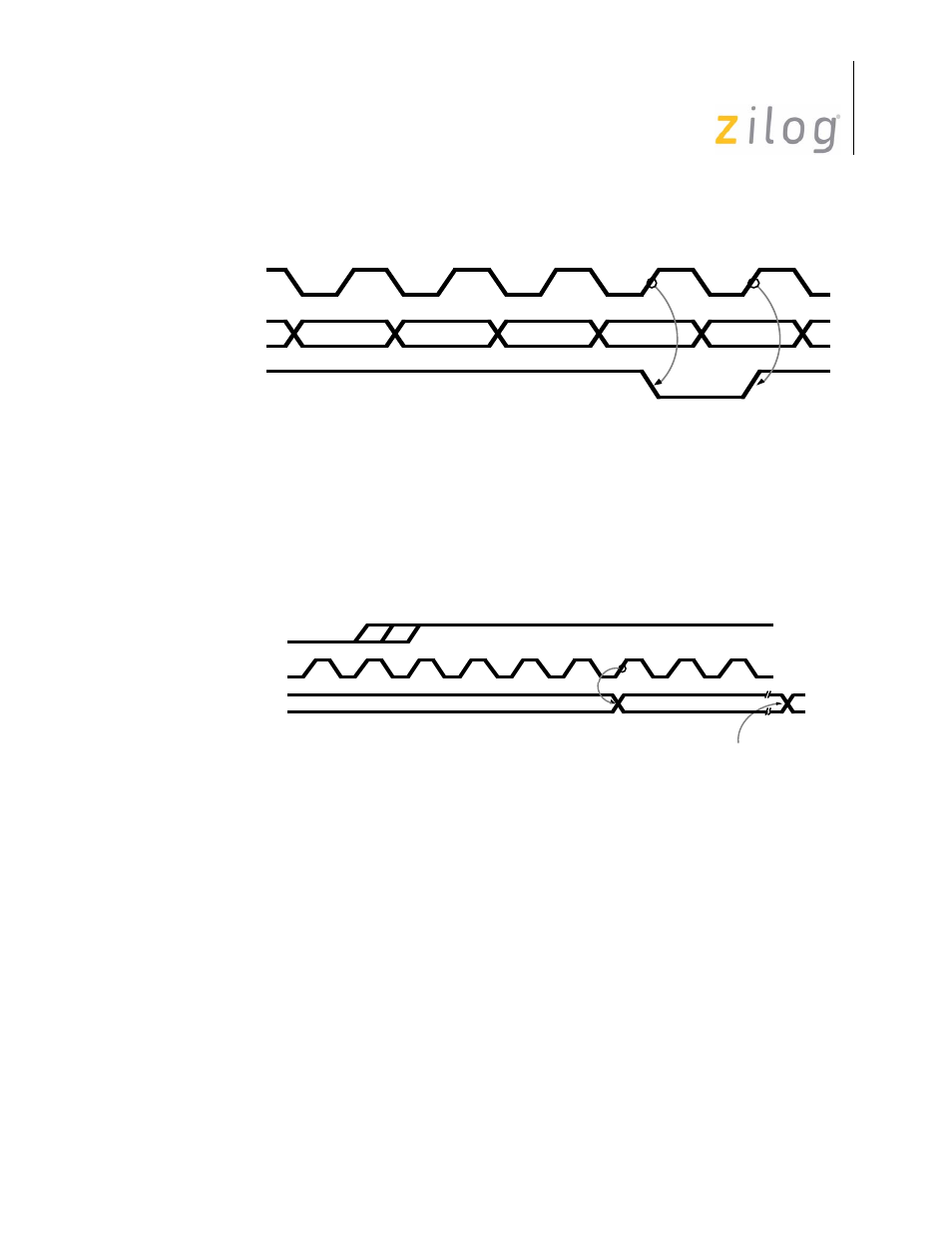
This is shown in Figure 4-6. The receiver leaves Hunt mode when /SYNC is driven Low.
Figure 4–21. /SYNC as an Input
In all cases except External Sync mode the /SYNC pin is an output that is driven low by
the ISCC to signal that a sync character has been received. The /SYNC pin is activated
regardless of character boundaries so any external circuitry using it should only respond
the /SYNC pulse that occurs while the receiver is in Hunt mode. The timing for the
/SYNC signal is shown in Figure 4-7.
Figure 4–22. /SYNC as an Output
It is sometimes desirable to prevent sync characters from entering the receive data FIFO.
This function is available in the ISCC by setting the Sync Character Load inhibit bit (D1)
in WR3 to “1”. While this bit is set to “1”, the character about to be loaded into the receive
data FIFO is compared with the contents of WR6. If all eight bits match the character, it is
not loaded into the receive data FIFO. Because the comparison is across eight bits, this
function works correctly only when the number of bits per character is the same as the
sync character length. Thus it cannot be used with 12- or 16-bit sync characters. Both lead-
ing sync characters and sync characters embedded in the data may be properly removed in
the case of a 8-bit sync character. Care must be exercised in using this feature because
sync characters not transferred to the receive data FIFO will automatically be excluded
from CRC calculation. This works properly only in the 8-bit case.
/RTxC
RxD
/SYNC
SYNC
SYNC
DATA
0
DATA
1
DATA
2
Last-
Las
State changes in one
/RTxC clock cycle
/RTxC
PCLK
/SYNC
Page 61 of 316