5 digital phase-locked loop (dpll), Digital phase-locked loop (dpll) – Zilog Z16C35 User Manual
Page 39
ISCC
User Manual
UM011002-0808
33
Manchester encoding, which is not directly supported, always produces a transition at the
center of the bit cell. If the transition is Low to High, the bit is “0.” If the transition is High
to Low, the bit is “1.” ISCC can be used to decode Manchester (biphase level) data by
using the DPLL in the FM mode and programming the receiver for NRZ data. (See section
3.5.3.)
The data encoding method should be selected in the initialization procedure before the
transmitter and receiver are enabled, but no other restrictions apply. Note, in Figure 3-3,
that in NRZ and NRZI the receiver samples the data only on one edge. However, in FM1
and FM0 the receiver samples the data on both edges. Also, as shown in Figure 6-4, the
transmitter defines bit cell boundaries by one edge in all cases and uses the other edge in
FM1 and FM0 to create the mid-bit transition.
3.5 DIGITAL PHASE-LOCKED LOOP (DPLL)
Each channel of the SCC cell contains a digital phase-locked loop that can be used to
recover clock information from a data stream with NRZI, FM or NRZ encoding. The
DPLL is driven by a clock nominally 32 (NRZI) or 16 (FM) times the data rate. The DPLL
uses this clock, along with the data stream, to construct a receive clock for the data. This
clock can then be used as the ISCC receive clock, the transmit clock, or both.
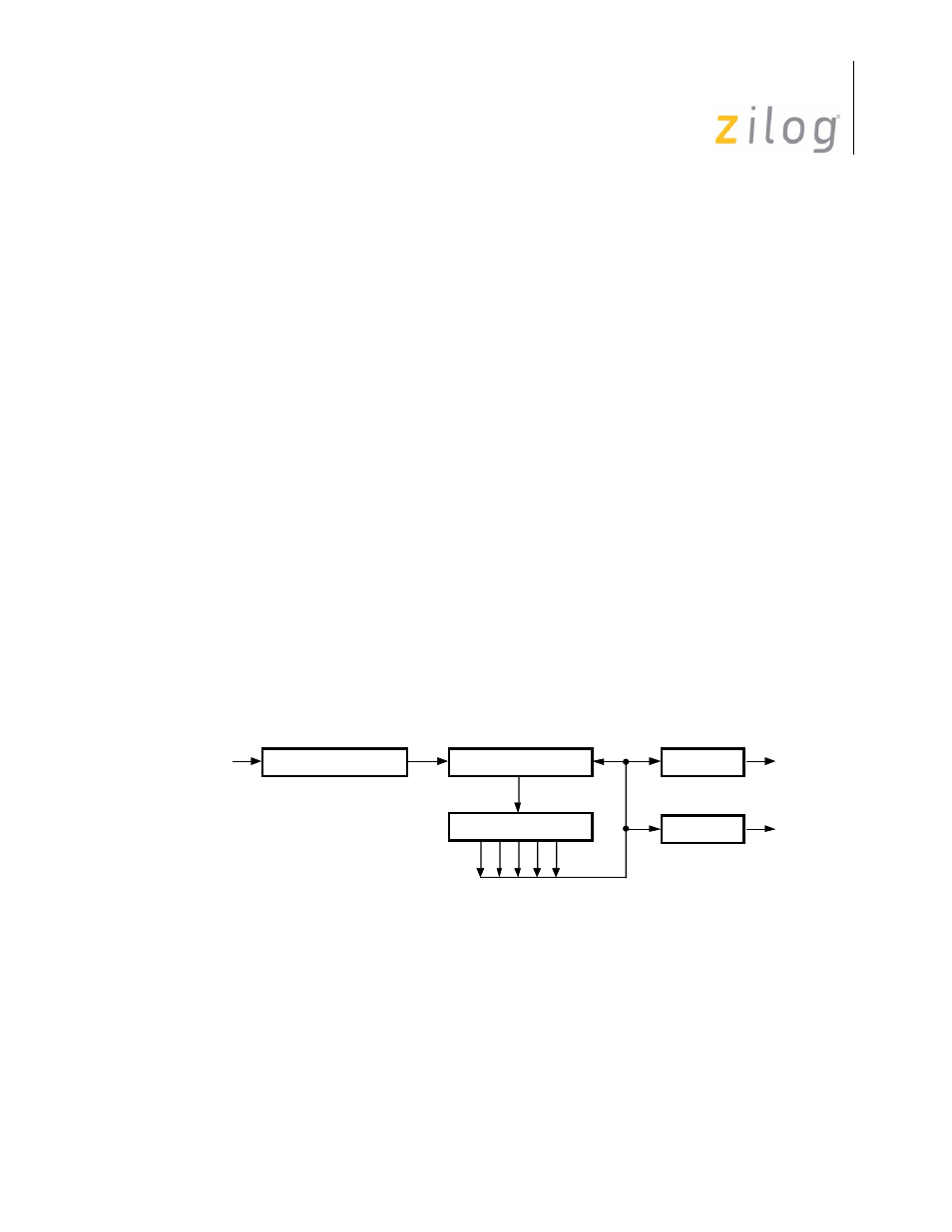
Figure 3-4 shows a block diagram of the digital phase-locked loop. It consists of a 5-bit
counter, an edge detector, and a pair of output decoders. The clock for the DPLL comes
from the output of a two-input multiplexer, and the two outputs go to the transmitter and
receive clock multiplexers. The DPLL is controlled by the seven commands that are
encoded in bits D7, D6 and D5 of WR14.
Figure 3–7. Digital Phase Lock Loop
The clock for the DPLL is selected by two of the commands in WR14, that is:
WR14 (7-5) = 100
BRG Clock Source
WR14 (7-5) = 101
/RTxC Pin Clock Source
Edge Detector
RxD
Count Modifier
Decode
Receive
Clock
5-Bit Counter
Decode
Transmit
Clock
Page 33 of 316