8 dma control register, Dma control register – Zilog Z16C35 User Manual
Page 144
ISCC
User Manual
UM011002-0808
138
Bit 7, when set to 1, enables the Receive A DMA.
Bit 6, when set to 1, enables the Transmit A DMA.
Bit 5, when set to 1, enables the Receive B DMA.
Bit 4, when set to 1, enables the Transmit B DMA.
Bit 3, when set to 1, enables the interrupt in the Receive A DMA Channel that is generated
when a DMA operation in this channel is aborted.
Bit 2, when set to 1, enables the interrupt in the Transmit A DMA Channel that is gener-
ated when a DMA operation in this channel is aborted.
Bit 1, when set to 1, enables the interrupt in the Receive B DMA Channel that is generated
when a DMA operation in this channel is aborted.
Bit 0, when set to 1, enables the interrupt in the Transmit B DMA Channel that is gener-
ated when a DMA operation in this channel is aborted.
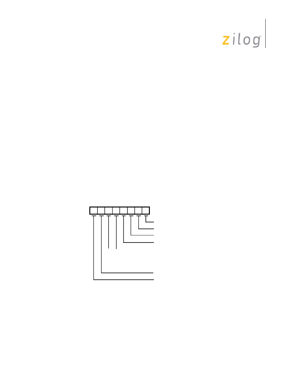
5.6.8 DMA Control Register
This register controls DMA priorities, requests, and address generation. The bit positions
for this register are shown in Figure 5-33.
Figure 5–62. DMA Control Register
Bit 7, when set to 1, enables a bus request per channel. This means that if more than one
DMA request is pending, after the completion of a DMA transfer from one DMA channel,
the bus will be relinquished and subsequently requested for the other channel DMA
requests. If this bit is cleared (0), the DMA will hold the bus until there are no DMA
Address: 00101
D6
D7
D5 D4 D3 D2 D1 D0
Tx B DMA Address Inc/Dec
Rx B DMA Address Inc/Dec
Tx A DMA Address Inc/Dec
Rx A DMA Address Inc/Dec
Reserved
Bus Request per Channel
Rx A/Tx A/Rx B/Tx B
Rx B/Tx B/Rx A/Tx A
Rx A/Rx B/Tx A/Tx B
Rx B/Rx A/Tx B/Tx A
0
0
1
1
0
1
0
1
DMA Priority
Page 138 of 316