Write register 5 (transmit parameter and controls) – Zilog Z16C35 User Manual
Page 109

ISCC
User Manual
UM011002-0808
103
5.4.6 Write Register 5 (Transmit Parameter and Controls)
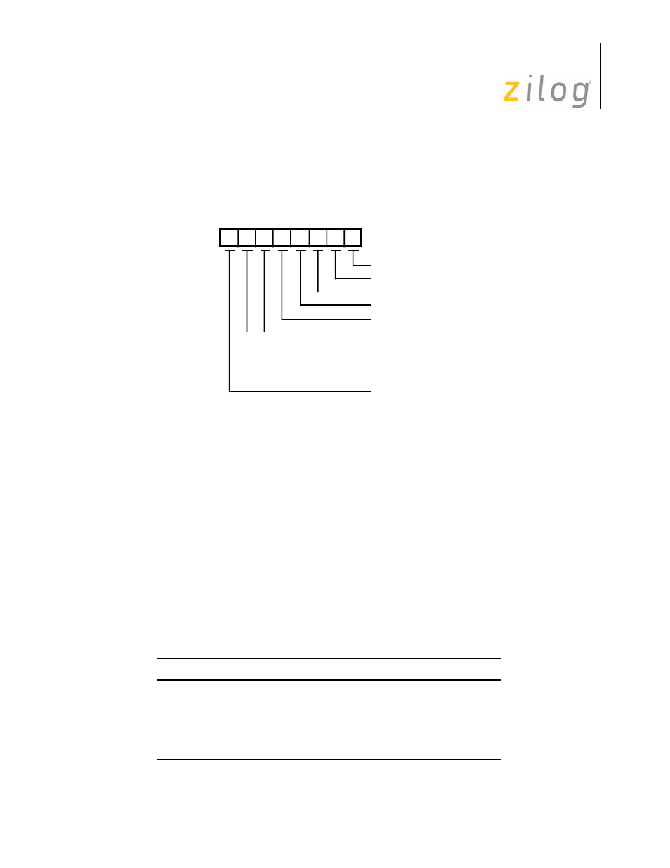
WR5 contains control bits that affect the operation of the transmitter. B2 affects both the
transmitter and the receiver. Bit positions for WR5 are shown in Figure 5-7.
Figure 5–36. Write Register 5
Bit 7 is the Data Terminal Ready control bit
This is the control bit for the /DTR//REQ pin while the pin is in the DTR mode (selected
in WR14). When set, /DTR is Low; when reset, /DTR is High. This bit is ignored when /
DTR//REQ is programmed to act as a /REQUEST pin. This bit is reset by a channel or
hardware reset. Refer to the description of Bit 2 in Write Register 14.
Bits 6 and 5 are the Transmit Bits/Character select bits 1 and 0
These bits control the number of bits in each byte transferred to the transmit buffer. Bits
sent must be right justified with least significant bits first.
The Five Or Less mode allows transmission of one to five bits per character; however, the
CPU should format the data character as shown below in Table 5-6. In the Six or Seven
Bits/Character modes, unused data bits are ignored.
Table 5–28. Transmit Bits per Character
Bit 7
Bit 6
Bits/Character
0
0
5 or less bits/character
0 1
7
bits/character
1 0
6
bits/character
1 1
8
bits/character
Write Register 5
D6
D7
D5 D4 D3 D2 D1 D0
Tx CRC Enable
RTS
/SDLC/CRC-16
Tx Enable
Send Break
DTR
Tx 5 Bits(Or Less)/Character
Tx 7 Bits/Character
Tx 6 Bits/Character
Tx 8 Bits/Character
0
0
1
1
0
1
0
1
Page 103 of 316
