2 asynchronous mode, Asynchronous mode – Zilog Z16C35 User Manual
Page 55
ISCC
User Manual
UM011002-0808
49
4.2 ASYNCHRONOUS MODE
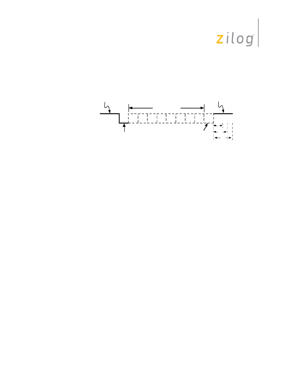
In asynchronous communications data is transferred in the format shown in Figure 4-3.
Figure 4–18. Asynchronous Message Format
The transmission of a character begins when the line makes a transition from the “1”
state, or MARK condition to the “0” state or SPACE condition. This transition is the refer-
ence by which the character’s bit cell boundaries are defined. Though the transmitter and
receiver have no common clock signal, there must be an agreement as to the data rate so
that the receiver can always sample the data in the center of the bit cell.
The character can be broken up into four fields:
8. Start bit - signals the beginning of a character frame.
9. Data field - typically 5-8 bits wide.
10. Parity bit - optional, provides mechanism for checking character validity, transmitter
and receiver agree that:
11. Data + Parity bit contains odd number of 1s (odd parity) or Data + Parity bit contains
even number of 1s (even parity).
Stop bit(s) - provides a minimum interval between the end of one character and the begin-
ning of the next.
The ISCC™ supports Asynchronous mode with a number of programmable options
including the number of bits per character, the number of stop bits, the clock factor,
modem interface signals and break detect and generation.
Asynchronous mode is selected by programming the desired number of stop bits in D3 and
D2 or WR4. Programming these two bits with other than “00” places both the receiver and
transmitter in Asynchronous mode. In this mode, the ISCC ignores the state of bits D4,
D3, and D2 of WR3, bits D5 and D4 of WR4, bits D2 and D0 of WR5, all of WR6 and
Idle State
of Line
LSB
1
0
Start
Bit
Parity
Bit
Data Field
Stop
Bit(s)
1.5
1
2
Page 49 of 316