Zilog Z16C35 User Manual
Page 52
ISCC
User Manual
UM011002-0808
46
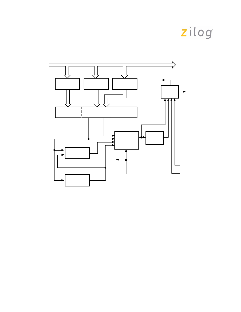
Figure 4–16. Transmitter Block Diagram
If asynchronous data is processed, WR6 and WR7 are not used and the Transmit Shift reg-
ister is formatted with start and stop bits shifted out to the transmit multiplexer at the
selected clock rate. Synchronous data (except SDLC/HDLC) is shifted to the CRC genera-
tor as well as to the transmit multiplexer.
SDLC/HDLC data is shifted to the CRC Generator and out through the zero insertion logic
(which is disabled while the flags are being sent). A “0” is inserted in all address, control,
information, and frame check fields following five contiguous “1s” in the data stream. The
result of the CRC generator for SDLC data is also routed through the zero insertion logic
and then to the transmit multiplexer.
RxD Delayed
One Bit
WR7 Sync
Register
WR6 Sync
Register
WR5 Transmit
Data
Final Tx
MUX
NRZI
Encode
RxD
Internal
TxD
To Other
Channel
Internal Data Bus
20-Bit
Transmit
Shift
Register
Start
Bit
SYNC
ASYNC
SDLC
CRC SDLC
CRC
Generator
Zero Insert
(5-Bits)
Transmit
MUX &
2-Bit Delay
TxD
Transmit
Clock
Page 46 of 316