3 dma registers, Dma registers – Zilog Z16C35 User Manual
Page 94
ISCC
User Manual
UM011002-0808
88
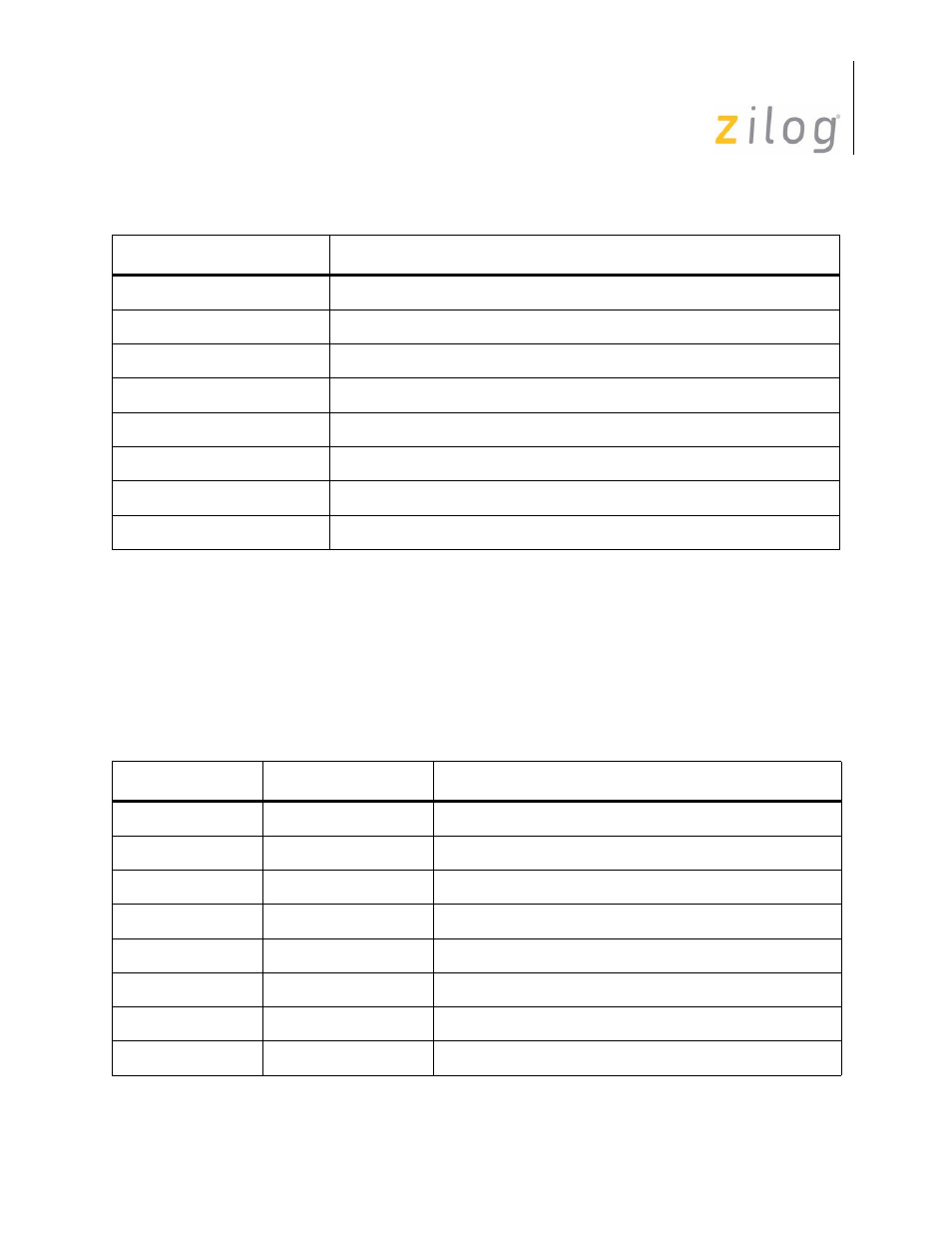
5.2.3 DMA Registers
The DMA cell contains 16 read write registers for control of the DMA channels. The
DMA possesses its own interrupt vector register and interrupt control registers which are
independent of the SCC cell. The DMA cell also includes the Bus Configuration Register
(BCR) for the ISCC. The addresses, names and descriptions of these registers are given in
Table 5-3.
RR3
Interrupt pending bits (Channel A only)
RR6
SDLC FIFO byte counter lower byte (only when enabled)
RR7
SDLC FIFO byte count and status (only when enabled)
RR8 Receive
buffer
RR10
Miscellaneous status bits
RR12
Lower byte of baud rate generator time constant
RR13
Upper byte of baud rate generator time constant
RR15 External
Status
interrupt information
Table 5–25. DMA Cell Register Description
Address
Name
Description
xxxxx
BCR
Bus Configuration Register
00000
CCAR
Channel Command/AddressRegister (Write)
00000
DSR
DMA Status Register (Read)
00001
ICR
Interrupt Control Register
00010
IVR
Interrupt Vector Register
00011
ICSR
Interrupt Command Register (Write)
00011
ISR
Interrupt Status Register (Read)
00100
DER
DMA Enable/Disable Register
Table 5–24. SCC Cell Read Registers
Register
Description
Page 88 of 316