1 write register 0 (command register), Write register 0 (command register) – Zilog Z16C35 User Manual
Page 96
ISCC
User Manual
UM011002-0808
90
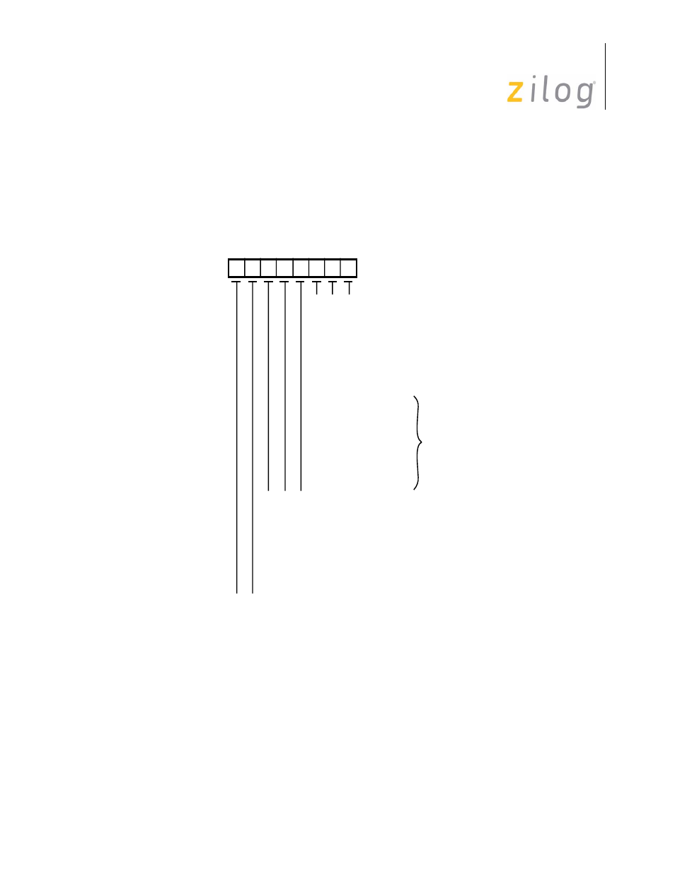
5.4.1 Write Register 0 (Command Register)
WR0 is the command register and the CRC reset code register. WR0 takes on slightly dif-
ferent forms depending upon whether the ISCC is in the multiplexed or non-multiplexed
bus mode of operation. Figure 5-1 shows the bit configuration for the non-multiplexed
mode and includes register select bits in addition to command and reset codes.
Figure 5–30. WR0 in the Non-Multiplexed Bus Mode
Write Register 0 (non-multiplexed bus mode)
D6
D7
D5 D4 D3 D2 D1 D0
Register 0
Register 1
Register 2
Register 3
Register 4
Register 5
Register 6
Register 7
Register 8
Register 9
Register 10
Register 11
Register 12
Register 13
Register 14
Register 15
0
0
1
1
0
0
1
1
0
0
1
1
0
0
1
1
0
1
0
1
0
1
0
1
0
1
0
1
0
1
0
1
0
0
0
0
1
1
1
1
0
0
0
0
1
1
1
1
Null Code
Point High
Reset Ext/Status Interrupts
Send Abort (SDLC)
Enable Int on Next Rx Character
Reset Tx Int Pending
Error Reset
Reset Highest IUS
0
0
1
1
0
0
1
1
0
1
0
1
0
1
0
1
0
0
0
0
1
1
1
1
Null Code
Reset Rx CRC Checker
Reset Tx CRC Generator
Reset Tx Underrun/EOM Latch
0
0
1
1
0
1
0
1
* With Point High Command
*
Page 90 of 316