Zilog Z16C35 User Manual
Page 49
ISCC
User Manual
UM011002-0808
43
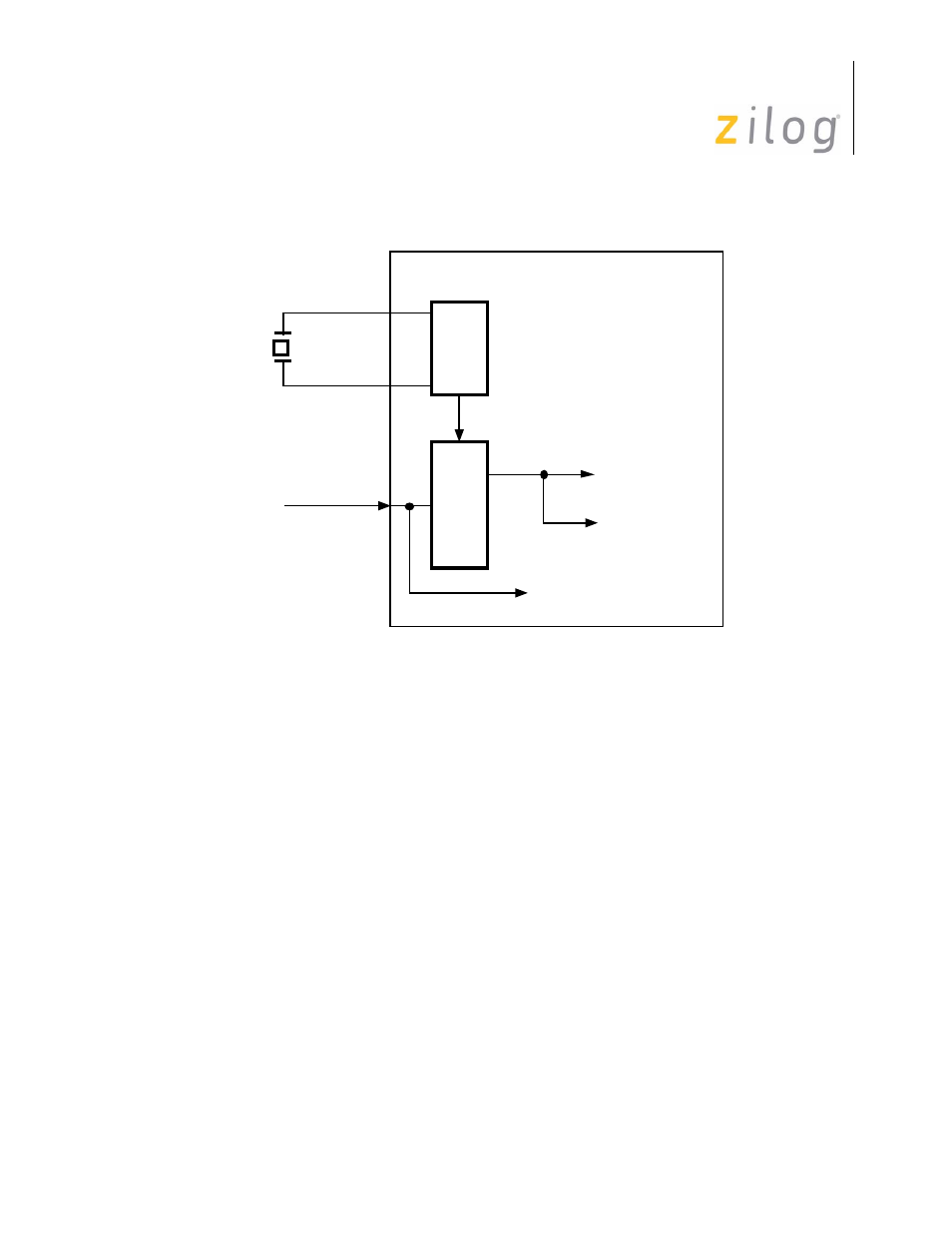
Figure 3–15. Asynchronous Transmission, 1x Clock Rate, FM Data Encoding
Fig 3-10 shows the clock set up for asynchronous transmission, 16x clock mode using the
on chip oscillator with an external crystal. The registers involved are WR11 and WR14
and the figure shows the programming in these registers. Figure 3-11 shows asynchronous
communication where a 1x clock is obtained from an external MODEM. The data encod-
ing is NRZ.
Note: that the BRG is not used under this configuration.
The x1 mode in Asynchronous mode is a combination of both synchronous and asynchro-
nous transmission. The data are clocked by a common timing base, but characters are still
framed with Start and Stop bits. Because the receiver waits for one clock period after
detecting the first High-to-Low transition before beginning to assemble characters, the
data and clock must be synchronized externally. The x1 mode is the only mode in which a
data encoding method other than NRZ may be used.
Figure 3-12 shows the use of the DPLL to derive a 1x clock from the data. In this exam-
ple:
•
The DPLL clock input = BRG output (x16 the data rate) WR14.
•
The DPLL clock output = RxC (receiver clock) WR11.
B
R
G
16x Data Rate
Txc
Rxc
/RTxC Pin
/SYNC Pin
External
Crystal
D
P
L
L
RxD Pin
RxD
Page 43 of 316