2 digital i/o supply (dvddio) monitor -16, 2 digital i/o supply (dvddio) monitor – Maxim Integrated MAXQ7666 User Manual
Page 88
MAXQ7665/MAXQ7666 User’s Guide
2-16
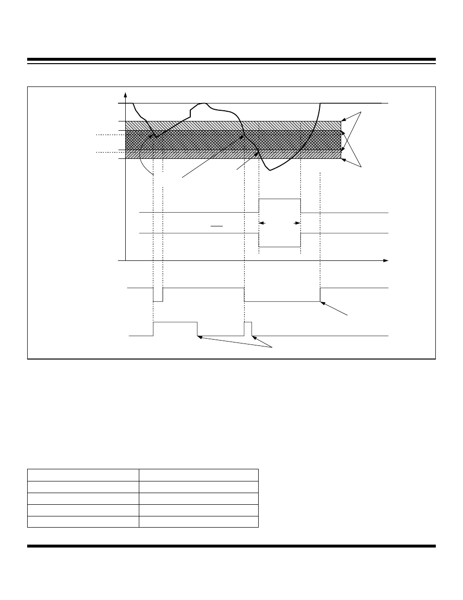
Figure 2-7. DVDD Brownout Interrupt Threshold Detection
NOMINAL
DVDD (+3.3V)
BROWNOUT
RESET TRIGGER
POINT
BROWNOUT
INTERRUPT TRIGGER
POINT
+3.13V
+3.06V
+2.84V
+2.77V
DGND
DVLVL FLAG
(ASR[14])
DVBI FLAG
(ASR[4])
DVDD
BROWNOUT
INTERRUPT
THRESHOLD RANGE
VDBI[1:0] = 01
DVDD BROWNOUT
RESET THRESHOLD
RANGE VDBR[1:0] = 01
BROWNOUT
RESET
INTERNAL RESET
BOR STATE
VDBE BIT SET BY
μC
FLAG ARBITRARILY
CLEARED BY
μC
RESET OUTPUT
BROWNOUT
INTERRUPT
2.6.2 Digital I/O Supply (DVDDIO) Monitor
The DVDDIO monitor detects a brownout condition on the +5V digital I/O supply. The DVDDIO supply monitor can be independently
activated by programming the corresponding enable bit (VIBE) in the APE register. A brownout is detected when the DVDDIO supply
voltage falls in the programmed DVDDIO brownout detection threshold range (Figure 2-8). The brownout interrupt threshold range is
user selectable, and can be programmed using the brownout interrupt threshold bits (VIOBI[1:0]) in the VMC register. The supported
threshold range are listed in Table 2-4. If enabled, an interrupt can be generated that allows for saving data and the present state of
the MAXQ7665/MAXQ7666. A DVDDIO brownout interrupt is generated only if the interrupt enable bit (VIOBIE) in the AIE register is
set. Also, global interrupt mask bits IM5 (in the IMR register) and IGE in (the IC register) must be enabled.
Table 2-4. DVDDIO Brownout Interrupt Threshold Range
VIOBI[1:0]
DVDDIO (V)*
00 (default)
4.25–4.74
01 4.30–4.79
10 4.35–4.84
11 4.40–4.89
* Reconfirm the values provided in this table with those in the latest MAXQ7665 and MAXQ7666 data sheets.
Maxim Integrated