4 baud-rate generation -15, 1 mode 0 baud rate -15, 2 mode 2 baud rate -15 – Maxim Integrated MAXQ7666 User Manual
Page 233: 3 mode 1 or 3 baud rate -15, Table 6-3. uart baud-clock summary -15, 4 baud-rate generation, Table 6-3. uart baud-clock summary, 1 mode 0 baud rate, 2 mode 2 baud rate, 3 mode 1 or 3 baud rate
MAXQ7665/MAXQ7666 User’s Guide
6-15
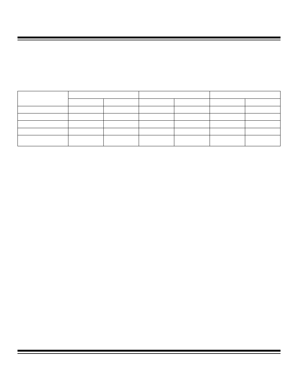
6.4 Baud-Rate Generation
Each mode of operation has a baud-rate generation technique associated with it. The baud-rate generation is affected by certain user
options such as the power management mode enable (PMME) bit, serial mode 2 (SM2) bit, and baud-rate doubler (SMOD) bit. Table
6-3 summarizes the effects of the various user options on the UART baud clock.
Table 6-3. UART Baud-Clock Summary
*
The baud frequency is determined by the baud-clock generator.
6.4.1 Mode 0 Baud Rate
Baud rates for mode 0 are driven directly from the system clock divided by either 12 or 4, with the default case being divide-by-12.
The user can select the shift clock frequency using the SM2 bit in the SCON0 register. When SM2 is set to logic 0, the baud rate is
fixed at divide-by-12 of the system clock. When SM2 is set to logic 1, the baud rate is divide-by-4 of the system clock.
Mode 0 Baud Rate = System Clock Frequency x (3
SM2
/ 12)
6.4.2 Mode 2 Baud Rate
In this asynchronous mode, baud rates are also generated from the system clock source. The user can effectively double the UART
baud-clock frequency by setting the SMOD bit to logic 1. The SMOD bit is set to logic 0 on all resets, thus making divide-by-64 the
default setting. The baud rate is given by the following formula:
Mode 2 Baud Rate = System Clock Frequency x (2
SMOD
/ 64)
6.4.3 Mode 1 or 3 Baud Rate
These asynchronous modes are commonly used for communication with PCs, modems, and other similar interfaces. The baud rates
are programmable using the baud-rate generator in the UART module. The baud-clock generator is basically a phase accumulator that
generates a baud clock as the result of phase overflow into the most significant bit of the phase shifter. This baud-clock generator is
driven by the system clock or system clock divided by 4 (depending upon the state of the SMOD bit). The baud-clock generator out-
put is always divided by 16 to generate the exact baud rate.
MODE 0
MODE 2
MODES 1, 3*
SYSTEM CLOCK MODE
SM2 = 0
SM2 = 1
SMOD = 0
SMOD = 1
SMOD = 0
SMOD = 1
Divide by 1
CLK/12
CLK/4
CLK/64
CLK/32
BAUD/64
BAUD/16
Divide by 2 (default)
CLK/24
CLK/8
CLK/128
CLK/64
BAUD/64
BAUD/16
Divide by 4
CLK/48
CLK/16
CLK/256
CLK/128
BAUD/64
BAUD/16
Divide by 8
CLK/96
CLK/32
CLK/512
CLK/256
BAUD/64
BAUD/16
Power Management Mode
(Divide by 256)
CLK/3072
CLK/1024
CLK/16384
CLK/8192
BAUD/64
BAUD/16
Maxim Integrated