Maxim Integrated MAXQ7666 User Manual
Page 165
MAXQ7665/MAXQ7666 User’s Guide
4-35
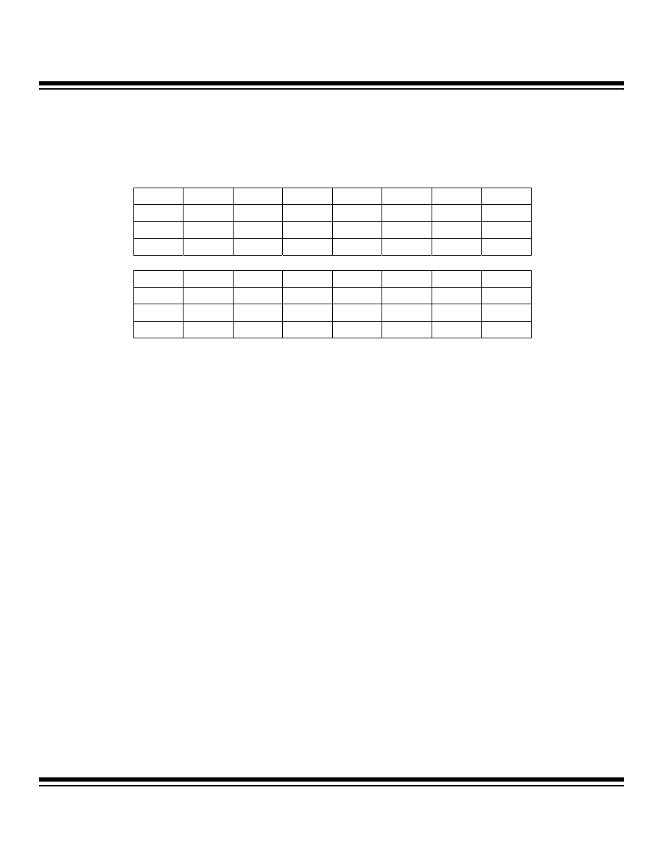
4.2.4.9 CAN 0 Receive Message Stored Register (C0RMS)
Register Description:
CAN 0 Receive Message Stored Register
Register Name:
C0RMS
Register Address:
Module 04h, Index 08h
Bit 15: Reserved. Read 0, write ignored.
Bits 14 to 0: CAN 0 Message Center 15 to 1 Receive and Store (C0RMS.15 to C0RMS.1). The C0RMS bits indicate which message
center (1 to 15) has successfully received and stored the last incoming message. The contents of the C0RMS register is updated each
time a new message is successfully received and stored. The contents of the C0RMS register are automatically cleared following each
read of C0RMS by the microcontroller. A bit value of 1 indicates that the assigned message center has successfully received and
stored new data since the last read of the C0RMS register. A bit value of 0 indicates no new messages have been successfully received
and stored since the last read of the C0RMS register. No interrupts are asserted because of the C0RMS settings. This register works
fully independent of the status bits in the CAN status register and the INTIN7:INTIN0 vector in the CAN interrupt register and inde-
pendent of the INTRQ bit in the CAN message control registers.
Bit #
15
14
13
12
11
10
9
8
Name
—
C0RMS.15 C0RMS.14 C0RMS.13 C0RMS.12 C0RMS.11 C0RMS.10 C0RMS.9
Reset
0 0 0 0 0 0 0 0
Access
r
r
r
r
r
r
r
r
Bit #
7
6
5
4
3
2
1
0
Name C0RMS.8
C0RMS.7
C0RMS.6
C0RMS.5
C0RMS.4
C0RMS.3
C0RMS.2
C0RMS.1
Reset
0 0 0 0 0 0 0 0
Access
r
r
r
r
r
r
r
r
r = read
Note: This register is cleared to 0000h on all forms of reset, including the reset established by the CRST bit.
Maxim Integrated