Maxim Integrated MAXQ7666 User Manual
Page 135
MAXQ7665/MAXQ7666 User’s Guide
4-5
The priority order associated with the CAN module transmitting or receiving a message is determined by the inverse of the number of
the message center, and is independent of the arbitration bits assigned to the message center. Thus, message center 2 has a higher
priority than message center 14. To avoid a priority inversion the CAN modules are configured to reload the transmit buffer with the
message of the highest priority (lowest message center number) whenever an arbitration is lost or an error condition occurs.
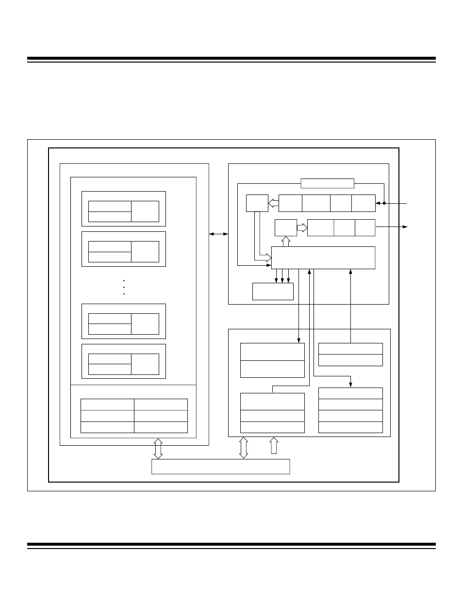
The MAXQ7665/MAXQ7666 CAN controller block diagram is shown in Figure 4-1.
Figure 4-1. MAXQ7665/MAXQ7666 CAN 0 Controller Block Diagram
CAN 0 CONTROLLER BLOCK DIAGRAM
DUAL PORT MEMORY
CAN PROCESSOR
CAN 0 PERIPHERAL REGISTERS
MESSAGE CENTERS 1-15
BUS ACTIVITY WAKEUP
8-BIT
Rx
CRC
CHECK
BIT
DESTUFF
Rx
SHIFT
BIT
TIMING
CANRXD
CANTXD
MESSAGE CENTER 2
ARBITRATION 0-3
FORMAT
DATA 0-7
MESSAGE CENTER 1
ARBITRATION 0-3
FORMAT
DATA 0-7
MESSAGE CENTER 15
CONTROL/STATUS/MASK REGISTERS
ARBITRATION 0-3
MEDIA ARBITRATION 0-1
EXT GLOBAL MASK 0-3
MEDIA ID MASK 0-1
STD GLOBAL MASK 0-1
BUS TIMING 0-1
MSG15 MASK 0-3
VIA C0DP/C0DB
MODULE/INDEX
FORMAT
DATA 0-7
MESSAGE CENTER 14
ARBITRATION 0-3
FORMAT
DATA 0-7
CAN 0 TRANSMIT MSG ACK
CAN 0 INTERRUPT REGISTER
CAN 0 STATUS REGISTER
CAN 0 RECEIVE MSG ACK
CAN 0 OPERATION CONTROL
CAN 0 CONTROL REGISTER
CAN 0 DATA POINTER
CAN 0 MESSAGE 1-15
CONTROL REGISTERS
CAN 0 DATA BUFFER
CAN 0 TRANSMIT ERROR
COUNTER
CAN 0 RECEIVE ERROR
COUNTER
CAN INTERRUPT
SOURCES
8-BIT
Tx
CRC
GENERATE
CAN
PROTOCOL
FSM
BIT
STUFF
Tx
SHIFT
TRANSPORT NETWORK
Maxim Integrated