3 dac control register (dcnt) -11, 3 dac control register (dcnt) – Maxim Integrated MAXQ7666 User Manual
Page 101
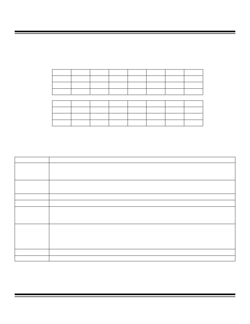
3.2.3 DAC Control Register (DCNT)
Register Description:
DAC Control Register
Register Name:
DCNT
Register Address:
Module 05h, Index 03h
Bits 15 to 7, 3 to 0: Reserved. Read returns 0, write ignored.
Bits 6 to 4: DAC Load Select Bits 2 to 0 (DACLD2 to DACLD0). These bits determine the mechanism of data transfer for DAC con-
version by generating the DACLOAD signal:
MAXQ7665/MAXQ7666 User’s Guide
3-11
Bit #
15
14
13
12
11
10
9
8
Name
— — — — — — — —
Reset
0 0 0 0 0 0 0 0
Access
r r r r r r r r
Bit #
7
6
5
4
3
2
1
0
Name
—
DACLD2 DACLD1 DACLD0
—
—
—
—
Reset
0 0 0 0 0 0 0 0
Access
r rw rw rw r r r r
r = read, w = write
Note: This register is cleared to 0000h on all forms of reset.
DACLD2:DACLD0
DATA TRANSFER
000
DAC conversion data is sourced from the DACO register under the control of the external DACLOAD input signal. On the rising
edge of the DACLOAD input, the DACO register is loaded with the contents of DACI register and converted. The DAC output signal
(DACOUT) then immediately tracks the DACO value. Note that this selection enables DACLOAD alternate function on the shared
DACLOAD/P0.5 pin.
001
DAC conversion data is sourced from the DACO register under the control of software write to DACI register. The DACO register is
loaded with the contents of DACI when the DACI register is written. The DAC output signal (DACOUT) then immediately tracks the
DACO value.
010 Reserved.
011
Reserved, functions as 001 if set.
100
DAC conversion data is sourced from the DACO register under the control of the external DACLOAD input signal. On the falling
edge of the DACLOAD input, the DACO register is loaded with the contents of DACI register and converted. The DAC output signal
(DACOUT) then immediately tracks the DACO value. Note that this selection enables DACLOAD alternate function on the shared
DACLOAD/P0.5 pin.
101
Square-wave mode. The data source for the DAC depends upon edges supplied by the DACLOAD pin.
1) A falling edge on DACLOAD after entering square-wave mode supplies the data in DACI to the DAC.
2) A rising edge on DACLOAD after entering square-wave mode supplies the data in DACO to the DAC.
The DAC output signal (DACOUT) tracks the DACI value on a falling edge and the DACO value on a rising edge. Note that as the
DAC settling time is up to 15
s, toggling DACLOAD at rates substantially faster than that may not allow the DAC to settle at either of
the intended output values.
110 Reserved.
111 Reserved.
Maxim Integrated