Maxim Integrated MAXQ7666 User Manual
Page 170
MAXQ7665/MAXQ7666 User’s Guide
4-40
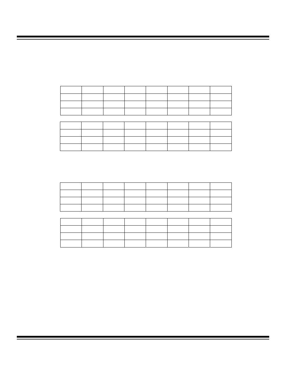
Note: The CAN 0 message center 2 to 15 control register bits are identical to those found in the CAN 0 message center 1 con-
trol register. Refer to these descriptions for the following registers.
Register Description:
CAN 0 Message Center 2 Control Register
Register Name:
C0M2C
Register Address:
Module 04h, Index 12h
Register Description:
CAN 0 Message Center 3 Control Register
Register Name:
C0M3C
Register Address:
Module 04h, Index 13h
Bit #
15
14
13
12
11
10
9
8
Name
— — — — — — — —
Reset
0 0 0 0 0 0 0 0
Access
r
r
r
r
r
r
r
r
Bit #
7
6
5
4
3
2
1
0
Name MSRDY
ETI
ERI
INTRQ
EXTRQ
MTRQ
ROW/TIH
DTUP
Reset
0 0 0 0 0 0 0 0
Access rw
rw
rw
rw
rc
r*
r*
r*
r = read, w = write, c = clear only, * = see description
Bit #
15
14
13
12
11
10
9
8
Name
— — — — — — — —
Reset
0 0 0 0 0 0 0 0
Access
r
r
r
r
r
r
r
r
Bit #
7
6
5
4
3
2
1
0
Name MSRDY
ETI
ERI
INTRQ
EXTRQ
MTRQ
ROW/TIH
DTUP
Reset
0 0 0 0 0 0 0 0
Access rw
rw
rw
rw
rc
r*
r*
r*
r = read, w = write, c = clear only, * = see description
Maxim Integrated