3 type 2 timer/counter operation modes -17, 3 type 2 timer/counter operation modes – Maxim Integrated MAXQ7666 User Manual
Page 252
MAXQ7665/MAXQ7666 User’s Guide
7-17
7.3 Type 2 Timer/Counter Operation Modes
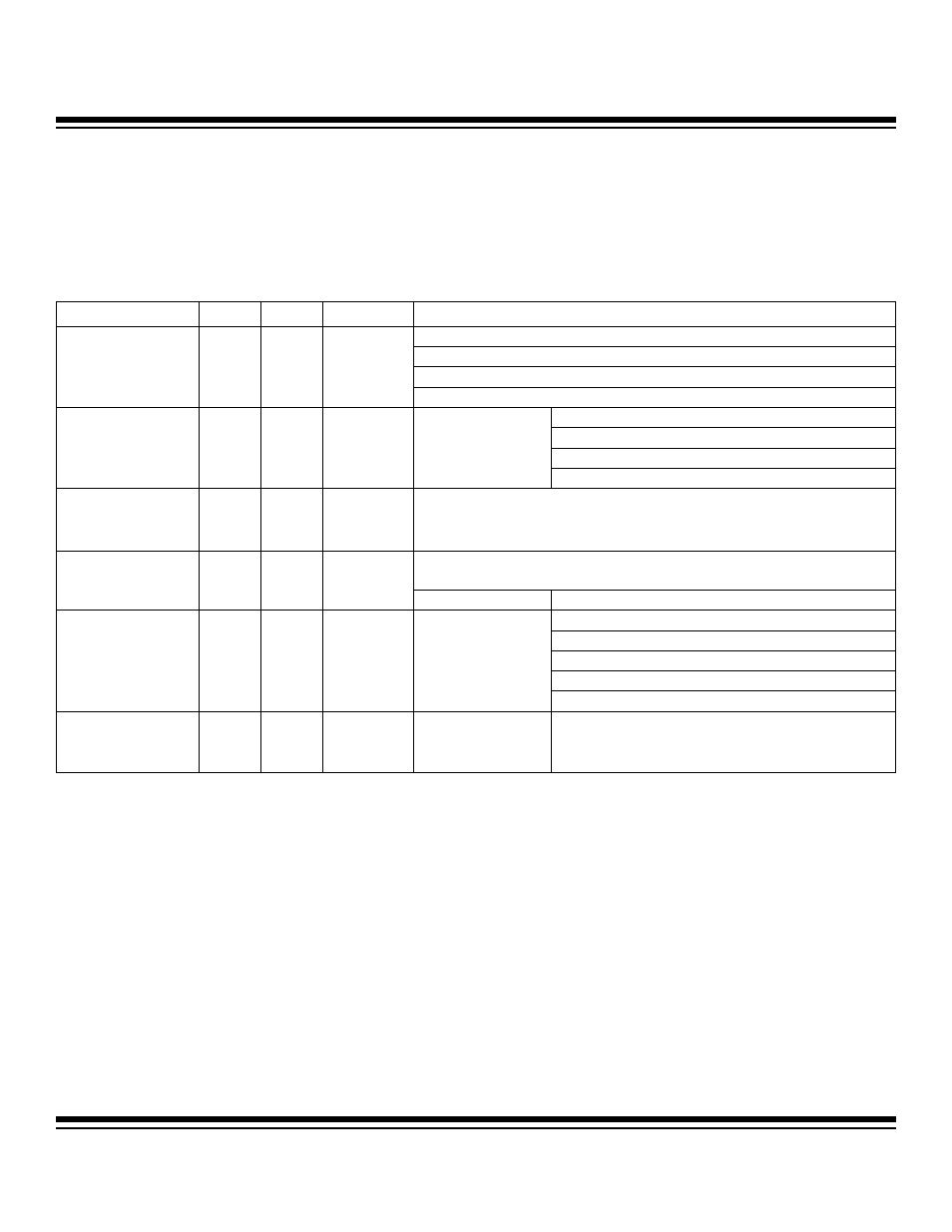
The MAXQ7665/MAXQ7666 Type 2 timer/counter supports six operation modes. Table 7-3 summarizes the modes supported by the
Type 2 timer and the peripheral register bits associated with those modes.
The Type 2 timer operating mode selection is illustrated in Figure 7-3. Figure 7-4 shows the PWM timer output possibilities.
Table 7-3. Type 2 Timer/Counter Functions and Control
MODE
T2MD
C/T2
CCF1:CCF0
CONTROL BITS
T2OE0: Output enable (PWM out)
T2POL0: Input/output polarity select
SS2: Single-shot pulse control
16-Bit Auto-
Reload/Compare Timer
0
0
00
G2EN: Gate timer clock
T2POL0: Gate level/reload edge select
SS2: Single-shot capture
G2EN: Gate timer clock (or gate reload)
16-Bit Capture
(CCF1:CCF0 bits define
capture edge)
0
0
01, 10, or 11
T2OE0 = 0
CPRL2: Reload enable
16-Bit Counter
(CCF1:CCF0 bits define
count edge)
0
1
01, 10, or 11
T2OE0 = 0
T2POL0: Output polarity select
T2OE0: Output enable (PWM out)
Dual 8-Bit Auto-Reload
Timers
1
0
00
T2Hx Only:
SS2: Single-shot pulse control
T2OE0 = 0
T2POL0: Gate level/reload edge select
SS2: Single-shot capture
G2EN: Gate timer (or gate reload)
8-Bit Capture and 8-Bit
Timer/PWM
(CCF1:CCF0 bits define
capture edge)
1
0
01, 10, or 11
T2Hx Only:
CPRL2: Reload enable
8-Bit Counter and 8-Bit
Timer/PWM
(CCF1:CCF0 bits define
count edge)
1
1
01, 10, or 11
T2Hx Only:
T2OE0 = 0
Note: Timer 2 in the MAXQ7665/MAXQ7666 does not support an input/output pin and serves only as an internal timer.
Maxim Integrated