3 system clock generation -12, 1 internal 7.6mhz rc oscillator -12, 3 system clock generation – Maxim Integrated MAXQ7666 User Manual
Page 209: 1 internal 7.6mhz oscillator
MAXQ7665/MAXQ7666 User’s Guide
5-12
5.3 System Clock Generation
All functional modules in the MAXQ7665/MAXQ7666 are synchronized to a single system clock. This system clock can be generated
from one of three possible sources:
• Internal 7.6MHz RC oscillator
• Internal high-frequency oscillator using external crystal or resonator circuit
• External high-frequency clock signal
Table 5-2 shows the registers and bits used to control clock generation and selection. For more information, see the register descrip-
tions in
Section 5.2.
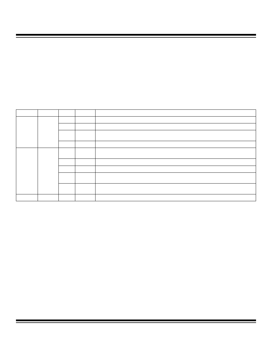
Table 5-2. Clock Generation and Selection Registers and Bits
5.3.1 Internal 7.6MHz Oscillator
The MAXQ7665/MAXQ7666 provide an internal 7.6MHz RC oscillator, which is used as the default source for the system clock follow-
ing any power-on reset or exit from stop mode. This oscillator, which requires no external components, typically runs at 7.6MHz. The
exact frequency may vary part to part and over temperature and supply voltage. For more details, refer to the MAXQ7665/
MAXQ7666 data sheet.
Following a power-on reset, to start up the internal oscillator the DVDD power supply must be above the minimum power-on reset
threshold of ˜1.2V and the external RESET must be deasserted (1). When the DVDD power supply crosses the ˜1.2V power-on reset
threshold, the internal 7.6MHz RC oscillator starts running and the 16-bit power-up counter is enabled. After 65,536 counts of the inter-
nal 7.6MHz RC oscillator (8.6ms typical), the power-up counter is disabled. The internal 7.6MHz RC oscillator is enabled as the sys-
tem clock (XT = 0, RGMD =1), and the MAXQ7665/MAXQ7666 start program execution at address 8000h in the utility ROM if the DVDD
power supply is above the power-on reset rising threshold level (2.7V–2.99V). Figure 5-2 illustrates the internal RC oscillator startup
and execution flow after a power-on reset. For more details on power-on reset, see
Section 2.
To select the 7.6MHz RC oscillator as the system clock source, the XT bit (CKCN.7) must be set to 0 and RCE must be set to logic 1.
Starting execution using the internal 7.6MHz RC oscillator requires a 4-cycle warmup delay under the following circumstances:
• After power-on reset
• After exiting stop mode
• After enabling the 7.6MHz RC oscillator (RCE = 1) and before switching the XT bit from a 1 to 0
REGISTER
ADDRESS
BIT
NAME
FUNCTION
[1:0]
CD[1:0]
Selects clock divide-by-1 (00), by-2 (01), by-4 (10), or by-8 (11) mode.
2
PMME
Selects divide-by-256 mode (1) or normal clock divide mode (0).
5 RGMD
Read-only. Indicates if RC oscillator (1) or external crystal/clock (0) is currently being used to
provide the system clock.
CKCN M8[0Eh]
7
XT
Selects external crystal/clock (1) or internal RC (0) as the clock source.
0 HFE
Selects whether the internal high-frequency oscillator (for use with external crystal or resonator) is
enabled (1) or not (0).
1
RCE
Selects whether the internal RC oscillator is enabled (1) or not (0).
2
EXTHF
Selects whether the external high-frequency clock (direct input) is enabled (1) or not (0).
[9:8] HFIC[1:0]
MAXQ7665: Selects the input capacitance of the on-chip high-frequency oscillator.
MAXQ7666: Selects both the input and output capacitance of the on-chip high-frequency oscillator.
OSCC M5[0Ch]
[11:10] HFOC[1:0]
MAXQ7665: Selects the output capacitance of the on-chip high-frequency oscillator.
MAXQ7666: Selects the crystal drive strength of the on-chip high-frequency oscillator.
ASR
M5[0Bh]
11
XHFRY
Indicates if high-frequency oscillator warmup is complete (1) and ready. ASR read clears the bit.
Maxim Integrated